Signal flow and lake® processing, Signal flow, Level adjustments & mute points – Lab.gruppen PLM 20K44 User Manual
Page 25: Plm+ series operation manual rev 1.0.0, Figure 6.1: plm+ signal flow diagram, Input router stage input selection and mute, Module output stage mute and gain settings
6. Signal Flow and Lake® Processing
PLM+ SERIES Operation Manual rev 1.0.0
25
6. Signal Flow and Lake® Processing
6.1. Signal Flow
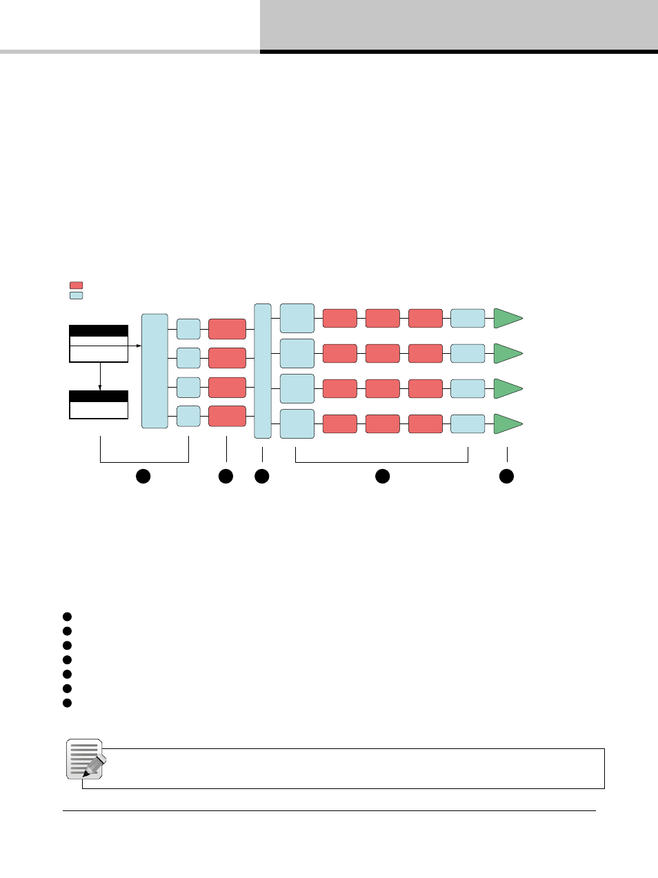
The figures below depict the audio signal flow for a PLM+ Series device. It is worth noting that this sophisticated
device provides seven points in the signal chain where the signal level can be adjusted, muted or disconnected.
The blue sections represent Frame data, and the red sections represent Module data - please refer to the Lake
Controller Operation Manual for further information.
Important information regarding correct setting of the gain structure can be found in section 10.3.
INPUTS
Dante Receivers 1-8
AES 1-4
Analog 1-4
OUTPUTS
Dante 1-8
(no mutes)
AES/Analog
pass through
to Dante
Input
Routers
1-4
WITH
INPUT
MUTES
Input
Mixer A
Input
Mixer B
Input
Mixer C
Input
Mixer D
Lake Contour
Module A
Attenuator
Mute
Phase Rev
Custom RPM
Lake Contour
Module B
Lake Contour
Module C*
Lake Contour
Module D*
ISVPL
Auto RPM
Amp Gain
LoadSmart
LoadPilot
AMP
Attenuator
Mute
Phase Rev
Custom RPM
ISVPL
Auto RPM
Amp Gain
LoadSmart
LoadPilot
AMP
Attenuator
Mute
Phase Rev
Custom RPM
ISVPL
Auto RPM
Amp Gain
LoadSmart
LoadPilot
AMP
Attenuator
Mute
Phase Rev
Custom RPM
ISVPL
Auto RPM
Amp Gain
LoadSmart
LoadPilot
AMP
Module Data stored in Module FIles (Speaker Presets)
Frame Data stored in System Files and Frame Presets
Output Routing
1
2
4
3
5
Figure 6.1: PLM+ Signal Flow Diagram
6.2. Level Adjustments & Mute Points
1
Input Router Stage
Input selection and MUTE
2
Input Mixer Stage
Router on /off connection to mixer and gain settings
3
Module Input Stage
Mute (N/A for LM Series Mesa Mode) and gain settings
4
Module Output Stage
Mute and gain settings
5
Output Router Stage
Output on /off routing connections
6
Attenuation Stage
Power output channel mute and attenuation settings
7
Amp Gain Stage
Amplifier gain control
Note: If the required audio signal is not passing correctly, verify the connection, mute and gain settings
at all seven stages.