Back panel interface, Binding post connectors, Plm+ series operation manual rev 1.0.0 – Lab.gruppen PLM 20K44 User Manual
Page 59: Figure 8.5: speakon nl4/nl8 configuration, Figure 8.6: binding post configuration
8. Back Panel Interface
PLM+ SERIES Operation Manual rev 1.0.0
59
3+
2-
4+
2+
1-
1+
4-
3-
1+
2 -
3+
4 -
NL4
PLM+ Output
Channels 1 & 2
NL4
PLM+ Output
Channels 3 & 4
NL8
PLM+ Output
Channels 1 - 4
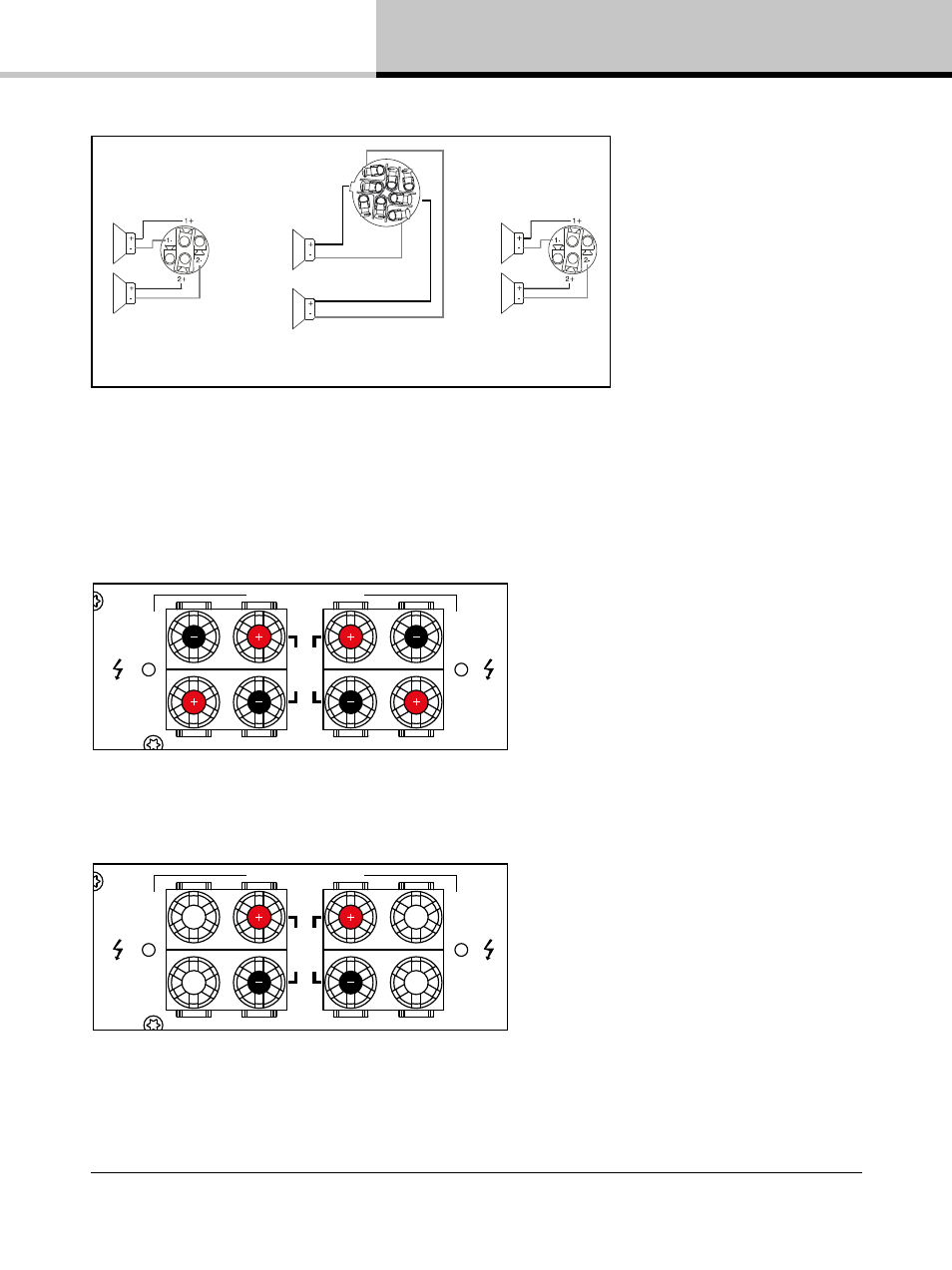
Figure 8.5: speakON NL4/NL8 Configuration
8.1.3. Binding Post Connectors
Binding post versions of the PLM+ are fitted with four pairs of black and red 4 mm binding posts.
CH
2
CH
1
CH
4
CH
3
SPEAKER OUTPUTS
CLASS 3 WIRING
BRIDGE
BRIDGE
Figure 8.6: Binding Post Configuration
CH
2
CH
1
CH
4
CH
3
SPEAKER OUTPUTS
CLASS 3 WIRING
BRIDGE
BRIDGE
Figure 8.7: Binding Post Configuration (Bridge Mode)
This manual is related to the following products: