Application guide 78, Analog input gain structure examples – Lab.gruppen PLM 20K44 User Manual
Page 78
10. Application Guide
78
PLM+ SERIES Operation Manual rev 1.0.0
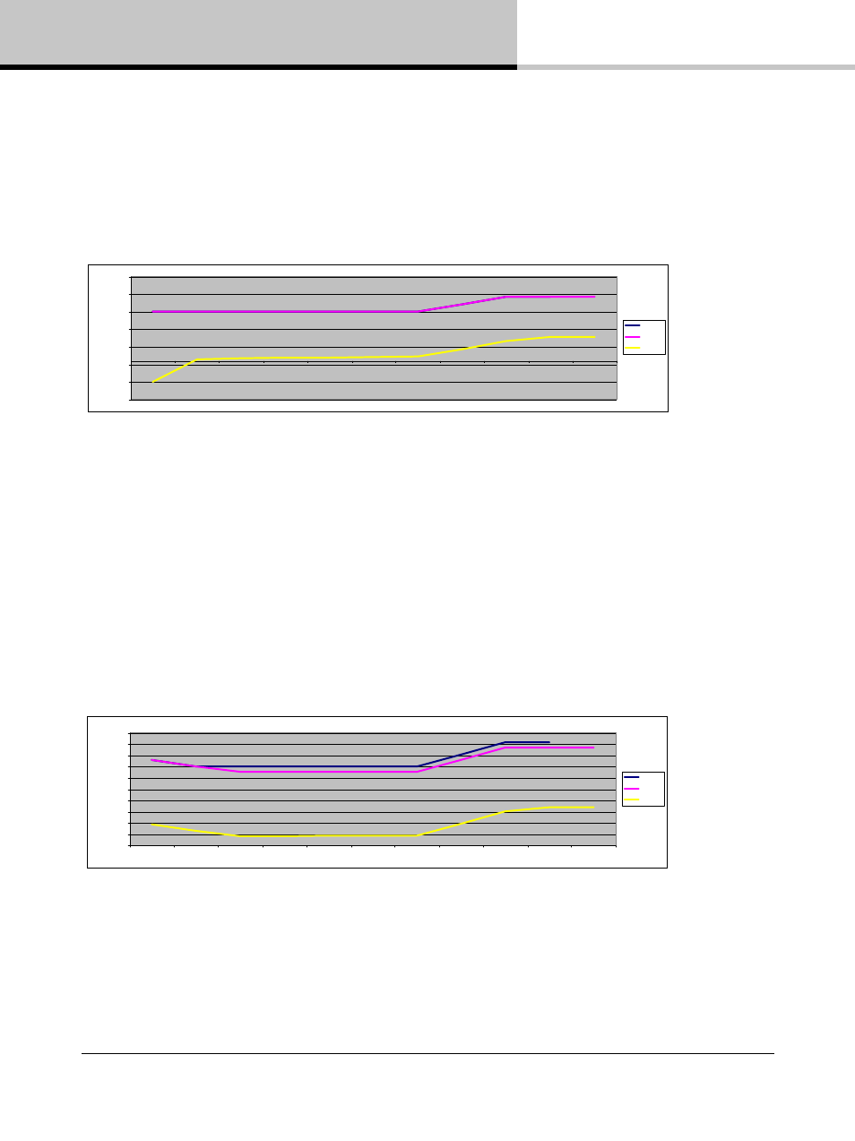
Figure 10.3 illustrates how to achieve the lowest possible output noise, although this is not a recommended
configuration.
• Input Clip: 0 dBFS
• Amp Gain: 22 dB
• SNR: 114.8 dB
• Absolute Noise Floor: -71.9 dBu
Table 10.3: Digital Input Optimized for Minimum Noise - Not Recommended
The improvement in noise performance (at the cost of losing headroom and compression features) is only 0.6 dB;
it is therefore not recommended to optimize performance in this manner.
10.4.3.2. Analog Input Gain Structure Examples
Figure 10.4 illustrates how to minimize absolute noise while limiting the available SPL. Input Clip: 12 dBu
• Amp Gain: 22 dB
• SNR: 105.5 dB
• Absolute Noise Floor: -71.5 dBu
• SPL is limited to -8.9 dB relative to clip in this minimum absolute noise level example
Table 10.4: Analog: Low Noise with Limited Output (Low Input / Low SPL)
-250,0
-200,0
-150,0
-100,0
-50,0
0,0
50,0
100,0
Analog
AES Input
Input Mixer
Module In
Module Out
Amp
Attenuation
Analog Ref
Amp Gain
ISVPL
Output
dB
/d
B
u
Clip
Nominal
Noise
-140,0
-120,0
-100,0
-80,0
-60,0
-40,0
-20,0
0,0
20,0
40,0
60,0
Analog
AES Input
Input Mixer
Module In
Module Out
Amp
Attenuation
Analog Ref
Amp Gain
ISVPL
Output
dB
/d
B
u
Clip
Nominal
Noise