Back panel interface 60, Analog inputs, Analog input xlr connections – Lab.gruppen PLM 20K44 User Manual
Page 60: Analog & aes3 xlr wiring and pin out
8. Back Panel Interface
60
PLM+ SERIES Operation Manual rev 1.0.0
Connect the ‘+’ loudspeaker terminals to the red binding posts and the ‘ – ‘ terminals to the black binding posts.
There are three methods of connecting speaker cables to the binding posts.
1. Solder 4 mm banana-plugs to the ends of the speaker wires and plug into the center of the turrets.
2. Thread the stripped ends of the wires through the holes in the posts. Enter the wires for output channels 1 and
3 from above and for channels 2 and 4 from below. Tighten the plastic turrets by finger only, being careful not to
overtighten.
3. Crimp 4 mm insulated spade terminals onto the ends of the wires and push into the binding post assembly
from above (Ch. 1 & 3) or below (Ch. 2 & 4). The hole in the post is ignored. Hand tighten plastic turrets, being
careful not to overtighten.
8.2. Analog Inputs
8.2.1. Analog Input XLR Connections
2
Four electronically balanced analog inputs are provided via latching XLR3F connectors.
INPUT 1
INPUT 2
INPUT 3
PIN 1: SCRN 2: POS 3: NEG
ANALOG WITH
I
SO-
F
LOAT
TM
INPUT 4
Figure 8.8: Analog Input XLR Connections
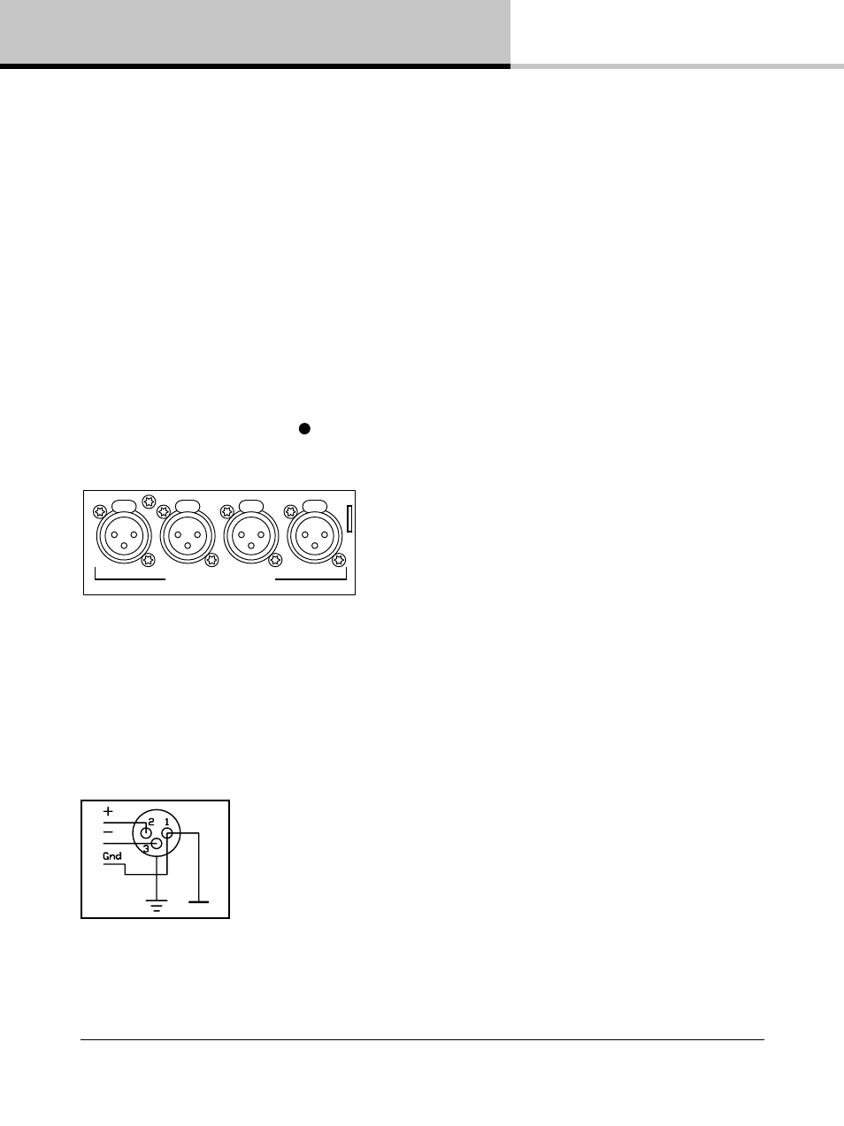
8.2.2. Analog & AES3 XLR Wiring and Pin Out
All XLR connections are wired to IEC268 as shown in Figure 8.9.
Figure 8.9: IEC268 XLR Wiring and Pin Out
Pin 1: Ground / Shield
Pin 2: Hot (+)
Pin 3: Cold (-)