Operation and performance, Plm+ series operation manual rev 1.0.0 – Lab.gruppen PLM 20K44 User Manual
Page 23
5. Operation and performance
PLM+ SERIES Operation Manual rev 1.0.0
23
This protection system recognizes only continuous VHF signals at high levels that will not appear in speech or
music. Any such content can therefore be considered as a fault condition. VHF protection is essential to avoid
damage to HF drivers.
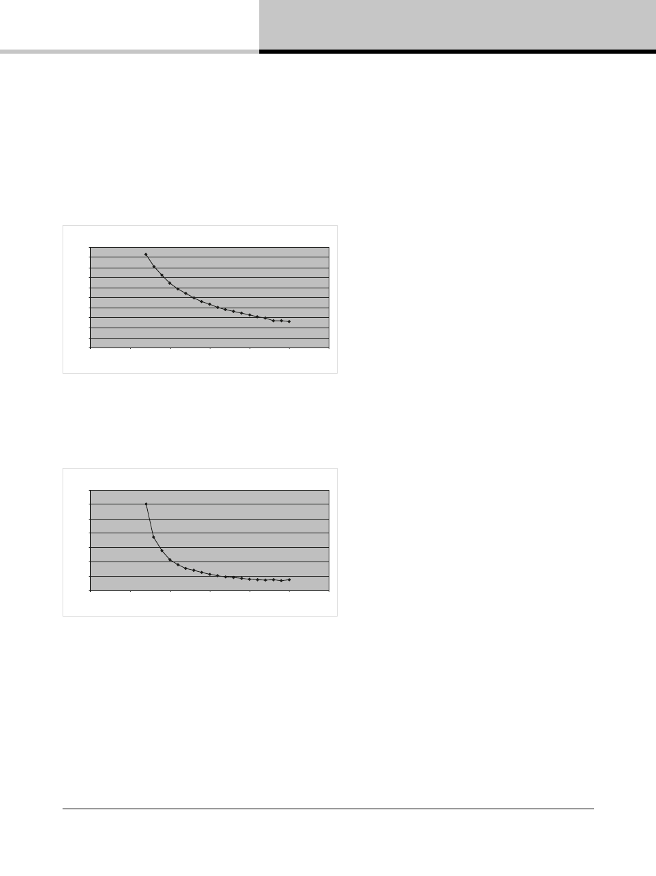
VHF protection is dependent on a combination of output power level and frequency. Figure 5.4 shows a
decreasing power threshold, from approximately 10 kHz upwards, which illustrates increasing sensitivity of the
protection system with frequency. When continuous output power above the threshold line is detected, VHF
protection becomes active.
Trigger voltage
Voltage [V
rms]
100
90
80
70
60
50
40
30
20
10
0
0
5
10
15
20
25
30
Frequency [kHz]
Fig 5.4: VHF Protection Frequency Sensitivity
The attack time of the VHF protection circuitry also changes with frequency, becoming shorter at higher
frequencies. This is shown in Figure 5.5.
Full output voltage
Time [ms]
1400
1200
1000
600
800
400
20
200
0
0
5
10
15
20
25
30
Frequency [kHz]
Fig 5.5: VHF Protection Attack Time Variations
The VHF protection circuit is NOT a limiter and does not alter the PLM+’s frequency response. It is implemented
solely to detect continuous VHF content. HF content of normal music or speech signals at peak levels will be
passed in full.
Operation of the VHF protection circuits is indicated by one (or more) of the output channel LEDs (in the right-hand
soft function buttons) showing steady red. The adjacent fault message will show VHF FAULT. It is also reported as
a fault via the control network.