Product overview 14, Rear panel, Plm+ series operation manual rev 1.0.0 – Lab.gruppen PLM 20K44 User Manual
Page 14
4. Product Overview
14
PLM+ SERIES Operation Manual rev 1.0.0
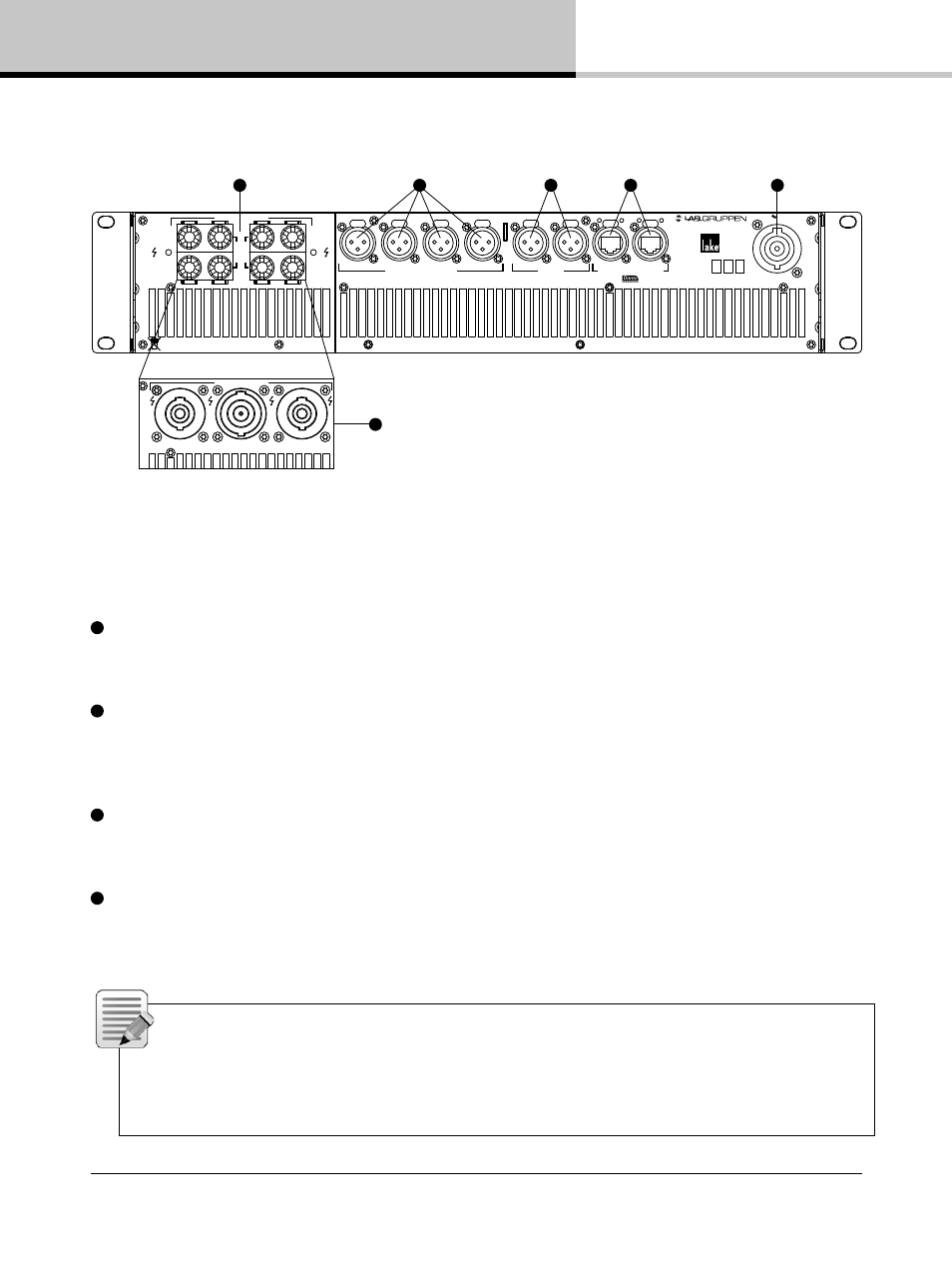
4.2. Rear panel
3
4
5
1
2
INPUT 1
INPUT 2
INPUT 3
AES/EBU
INPUT 1-2
INPUT 3-4
SEC
PRIM
Must be grounded/earthed
Made in Sweden
PIN 1: SCRN 2: POS 3: NEG
ANALOG WITH
I
SO-
F
LOAT
TM
50-60Hz
100-240V 2400-2950W
Ser. N:o
Removed!
CH
2
CH
1
CH
4
CH
3
SPEAKER OUTPUTS
CLASS 3 WIRING
BRIDGE
BRIDGE
INPUT 4
SWITCHED 00/ 000 Base-TX
1 1
1Gbps
1Gbps
LINK
ACT
LINK
ACT
PLM 2K44
1
1+/- CH 1+/-
2+/- CH 2+/-
1+/- CH 1+/-
2+/- CH 2+/-
3+/- CH 3+/-
4+/- CH 4+/-
1+/- CH 3+/-
2+/- CH 4+/-
CLASS 3
WIRING
BRIDGE CH 1 & 2:
1+:+
2- : -
BRIDGE CH 3 & 4: 1+ : +, 2- : -
SPEAKER OUTPUTS
INPUT 1
INPUT 2
INPUT 3
AES/EBU
INPUT 1-2
INPUT 3-4
SEC
PRIM
Must be grounded/earthed
Made in Sweden
PIN 1: SCRN 2: POS 3: NEG
ANALOG WITH
I
SO-
F
LOAT
TM
50-60Hz
100-240V 2400-2950W
INPUT 4
SWITCHED 00/ 000 Base-TX
1 1
1Gbps
1Gbps
LINK
ACT
LINK
ACT
PLM 2K44
1
6
The PLM+ is available with a choice of connectors for power outputs: binding posts or Neutrik speakON®. Both
connection methods allow for Bridge Mode operation, which is activated from the Lake Controller software. Please
refer to the Lake Controller Operation Manual and section 8.1.1 of this Operation Manual for further information on
Bridge Mode.
1
Binding Posts – In this version, the power outputs for loudspeaker connection are available on four separate
pairs of fully enclosed binding posts. Bridge Mode can be enabled via the Lake Controller software; please refer to
the Lake Controller Operation Manual for further information.
2
speakON Connectors – The power outputs are simultaneously available on a single 8-pole speakON
connector, and on two 4-pole speakON connectors. The two 4-pole connectors carry the outputs of channels 1
& 2 and 3 & 4 respectively. Bridge Mode can be enabled via the Lake Controller software. Please refer to the Lake
Controller Operation Manual.
3
Analog Inputs – Analog inputs are available on four standard XLR3F latching connectors. The inputs are
electronically balanced and feature Lake Iso-Float circuitry. The impedance is 20 kohms, and the inputs can accept
a maximum input level of +26 dBu.
4
AES3 Inputs – Two latching XLR3F connectors are provided for AES3 digital audio signals (four audio
channels). Input impedance is 110 ohms, please ensure that 110 ohm digital audio cables are used; standard XLR
microphone cables are rarely suitable for reliable digital audio transmission.
Note: The PLM+ does not provide Analog or AES loop through / Link connectors. Where needed,
it is recomended to use Y-split cables or patchpanels wired to connect the Inputs with Link output
connectors. The AES3 termination load shall be enabled when the PLM+ is the last unit connected
within an AES3 daisy-chained system. The termination may be disabled, if desired, via the front panel
menu and within the Lake Controller software.