Front panel interface 42, Input meters view, Module meters view – Lab.gruppen PLM 20K44 User Manual
Page 42
7. Front Panel Interface
42
PLM+ SERIES Operation Manual rev 1.0.0
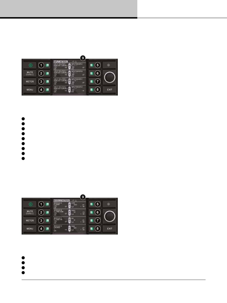
7.10.4. Input Meters View
Input View enables inspection of the source selected to each input router; input signal level before the input mixer
(i.e. prior to the Home View Module input meters); Module Input Mixer Routing; as well as Input Connection status.
Figure 7.11: Meter Mode > Input Meters View
1
Input Router 1: Selected input type, input gain level (relative to clip), router fault/warning/clip
2
Input Router 2: Selected input type, input gain level (relative to clip), router fault/warning/clip
3
Input Router 3: Selected input type, input gain level (relative to clip), router fault/warning/clip
4
Input Router 4: Selected input type, input gain level (relative to clip), router fault/warning/clip
5
Module A Input Mixer, Module A input level meter, Input 1 Connection Status
6
Module B Input Mixer, Module A input level meter, Input 1 Connection Status
7
Module C Input Mixer, Module A input level meter, Input 1 Connection Status
8
Module D Input Mixer, Module A input level meter, Input 1 Connection Status
9
Current View title & Frame label, Frame faults and warnings
7.10.5. Module Meters View
Module View provides further signal level information in the form of additional power output meters as
shown in Figure 7.12.
Figure 7.12: Meter Mode > Module Meters View
1
Module A label and input gain meter
2
Module B label and input gain meter
3
Module C label and input gain meter
4
Module D label and input gain meter