Application guide, Maximize volume capability, Minimize noise – Lab.gruppen PLM 20K44 User Manual
Page 77: Gain optimization examples, Digital input gain structure examples, Plm+ series operation manual rev 1.0.0
10. Application Guide
PLM+ SERIES Operation Manual rev 1.0.0
77
10.4. Gain / Level Optimization
10.4.1. Maximize Volume Capability
To maximize the volume capability of the device, ensure there is sufficient headroom in the signal path to avoid
clipping before the limiters engage. It must be possible to achieve enough gain through the device to engage
the limiters and realize a high average SPL. As an optimal setting, allow for a headroom of 10 dB or more for all
channels; the simplest way to accomplish this is to increase the Module input gain.
10.4.2. Minimize Noise
To help provide the best volume to noise ratio, use an AES or Dante digital input signal wherever possible. If using
analog inputs, ensure that unused or unnecessarily high headroom is not introduced at the input to the device. If
full or high average power is not required, the Module input gain may be reduced.
10.4.3. Gain Optimization Examples
This section provides examples on performance effects resulting from changes to the PLM+ gain structure
10.4.3.1. Digital Input Gain Structure Examples
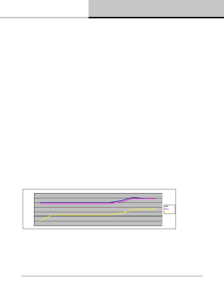
Figure 10.2 illustrates the recommended configuration of the PLM+ when using an AES or Dante digital input.
• Input Clip: 0 dBFS
• Amp Gain: 35 dB
• SNR: 114.2 dB
• Absolute Noise Floor: -71.3 dBu
Table 10.2: Digital Input: Low Noise with Good Headroom (High Input / High SPL)
-250,0
-200,0
-150,0
-100,0
-50,0
0,0
50,0
100,0
Analog
AES Input
Input Mixer
Module In
Module Out
Amp
Attenuation
Analog Ref
Amp Gain
ISVPL
Output
dB
/d
B
u
Clip
Nominal
Noise