Front panel interface 40, Amplifier meters view – Lab.gruppen PLM 20K44 User Manual
Page 40
7. Front Panel Interface
40
PLM+ SERIES Operation Manual rev 1.0.0
Note: Output limiter (gain reduction) meters take into account the sum of PLM+ ISVPL and Lake
LimiterMax.
10
The icons in the center of the LCD indicate the amplifier channel to which each module output is routed. When
two amplifier channels are Bridged, both channels will be displayed.
The type of icon used in the center of the screen confirms whether the PLM+ outputs are configured in Standard
mode or Bridge Mode, as shown in Figure 7.8 For further information on Bridge Mode, please refer to section
8.1.1.
Figure 7.8: Standard and Bridge Mode Front Panel Icons
Bridge Mode is visible via this icon notation on the PLM+ Front Panel in Home View, however, the Lake Controller
must be used to configure Bridge Mode; please refer to the Lake Controller Operation Manual for further
information.
Home View looks similar for most configurations, with slight variations dependant on the PLM+ model and
processor configuration.
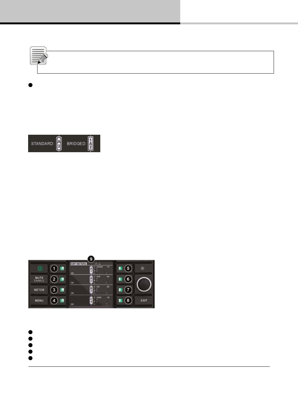
7.10.2. Amplifier Meters View
Amplifier Meters View provides further signal level information in the form of additional power output meters as
shown in Figure 7.9.
Figure 7.9: Meter Mode > Amplifier Meters View
1
Output 1: V - Voltage Meter I - Current Meter P - Power Meter L - Gain Reduction Meter
2
Output 2: V - Voltage Meter I - Current Meter P - Power Meter L - Gain Reduction Meter
3
Output 3: V - Voltage Meter I - Current Meter P - Power Meter L - Gain Reduction Meter
4
Output 4: V - Voltage Meter I - Current Meter P - Power Meter L - Gain Reduction Meter
5
LoadPilot Status: 1. High Freq Pilot tone Enabled/Disabled, 2. Low Freq Pilot tone Enabled/Disabled, Status