Datalogic Scanning Matrix 400 User Manual
Page 97
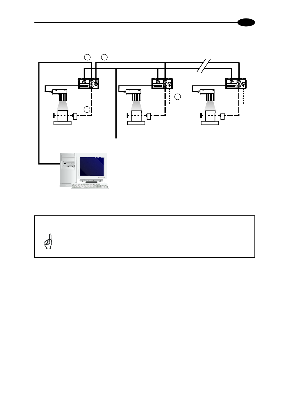
TYPICAL LAYOUTS
87
6
For a Master/Slave Multidata layout each reader has its own reading phase independent
from the others; each single message is sent from the master reader to the Host computer.
Figure 105 – ID-NET™ M/S Multidata
NOTE
The auxiliary serial interface of the slave readers can be used in Local Echo
communication mode to control any single reader (visualize collected data)
or to configure it using the VisiSet™ utility.
The ID-NET™ termination resistor switches must be set to ON only in the first
and last CBX connection box.
Terminal
Main Serial Interface (RS232 or RS485)
Auxiliary Serial Interface (Local Echo) (RS232)
External Trigger (for One Shot or Phase Mode)
ID-NET™ (up to 32 devices, max network extension of 1000 m)
Host
1
4
3
2
Master Slave#1
Slave#n
Power