Maintenance – Glow-worm Ultracom2 35 Store User Manual
Page 60
0020112185_PROTO_13 - 01/11 - Glow-worm
- 58 -
19.7 PCb
i
When replacing the board refer to instructions
supplied with the spare part.
19.7.1
Main PCb
230
V
E
D
D
A
B
A
C
3
4
5
6
7
2
1
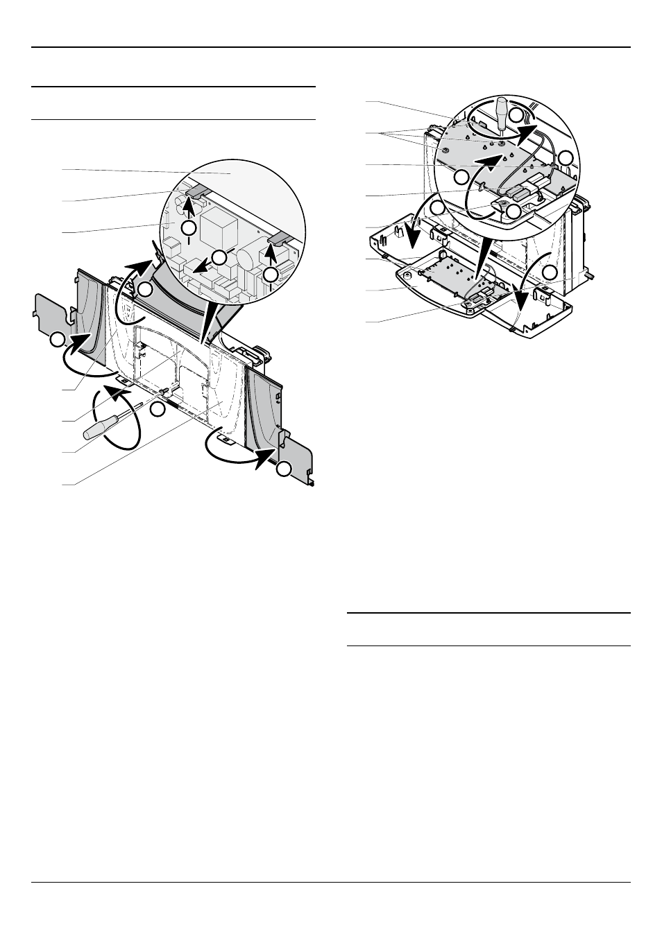
Key
1 230 V access cover
2 Screw
3 Main PCb access cover
4 24 V access cover
5 Main PCb
6 Retaining clips
7 Control Panel
• Remove the 24V and 230V connections.
• Open the covers (1;3;4).
• Ease back the two PCB retaining clips (6) and withdraw the
PCB from the retaining lugs.
• Remove the electrical connections to the PCB (appliance
interface cable).
19.7.2
2A fuse Rating
• For access, refer to chapter "Main PCB".
• The fuse is located at top right hand side of the PCB, see
chapter "Electrical connection ▸ Wiring diagram".
19.7.3
User interface PCb
230
V
A
A
B
C
D
E
1
2
3
4
5
6
6
7
Key
1 Control Panel
2 User interface
3 User interface PCb
4 Retaining screw
5 bracket (Switch On/Off)
6 Retaining clips
7 User interface PCb retaining screws
• Open the user interface (2).
• Remove the retaining screws (4;7) of the bracket (5).
• Ease back the two PCB retaining clips (6) and withdraw the
PCB from the retaining lugs.
• Remove the electrical connections to the PCB.
• When refitting the user interface, ensure the leads are not
trapped.
19.7.4
Mains supply cable
e
The main supply cable must be replaced by a
qualified and competent electrician.
• If the main supply cable is damaged, replace it refering to the
chapter "Electrical connection".
MAINTENANCE