Maintenance, 3 fault codes – Glow-worm Ultracom2 35 Store User Manual
Page 40
0020112185_PROTO_13 - 01/11 - Glow-worm
- 38 -
• Check that there is a gas supply to the boiler and the gas
service isolation valve is turned on.
• Check pressure at the gas service isolation valve.
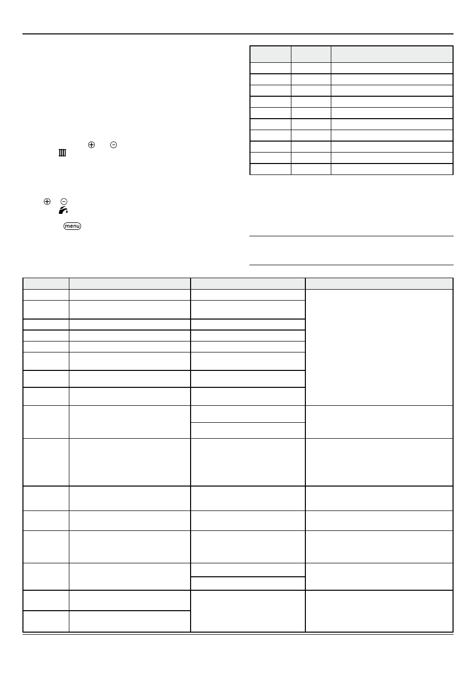
15.2 fault memory
• This menu allows you to display the 10 most recent failure
codes registered by the appliance.
• In order to display the fault code memory, simultaneously
press the buttons and of the
h
eating temperature
controls for more than 7 seconds.
• The screen will display the first fault "01" (record) and "F.XX"
(fault code).
• To display the other faults registered by the appliance, press
the or button
of the
d
omestic hot water temperature
controls .
• Press
the
button
for more than 3 seconds to exit this
menu.
Record
fault code Description
01
XX
Consult the “Fault codes” chapter.
02
XX
Consult the “Fault codes” chapter.
03
XX
Consult the “Fault codes” chapter.
04
XX
Consult the “Fault codes” chapter.
05
XX
Consult the “Fault codes” chapter.
06
XX
Consult the “Fault codes” chapter.
07
XX
Consult the “Fault codes” chapter.
08
XX
Consult the “Fault codes” chapter.
09
XX
Consult the “Fault codes” chapter.
10
XX
Consult the “Fault codes” chapter.
• To erase the fault memory registered by the appliance, consult
the “Installation adjustments” chapter and use code “d.94”.
15.3 fault codes
i
The faults described in this chapter should be carried
out by a qualified engineer and if needed by the After
Sales Service.
fault codes
Description
Cause
Solution
F00
Flow heating temperature sensor fault
Sensor open circuit
• Check the sensor’s connections.
• Check the wiring harness.
• Check the sensor.
F01
Return heating temperature sensor fault
Return heating temperature sensor
disconnected
F02
Hot water temperature sensor fault
Sensor disconnected
F03
Storage tank temperature sensor fault
Sensor disconnected
F10
Flow heating temperature sensor fault
Sensor short-circuit
F11
Return heating temperature sensor fault
Return heating temperature sensor
shorted.
F12
Hot water temperature sensor fault
Hot water temperature sensor short
circuit
F13
Storage tank temperature sensor fault
Storage tank temperature sensor short-
circuit
F20
Overheating fault
Overheating safety device activated
(97°C)
• Check the operation of the pump.
• Check the wiring harness.
• Check that the flow and return heating isolation
valves are open.
Improper bleeding
F22
Water pressure of the installation (<0.3
bar)
Return water valve closed
Pump disconnected
Leak in the installation
• Fill the installation.
• Purge the installation.
• Check the pump connections.
• Check the flow and return heating sensor
connections.
• Check that there are no leaks.
F23
Maximum temperature difference
reached between return and flow heating Water circulation fault
• Check the flow and return heating sensor
connection.
• Check the pump speed.
F24
Water circulation fault
Malfunction of the pump (excessively
rapid temperature increase)
• Check that the flow and return heating isolation
valves are open.
F26
Fault in gas valve motor.
Disconnected or defective cables
• Check the gas valve connections.
• Check the operation of the gas valve.
• Check the operation of the condensate pump
(option).
F27
Flame detection fault.
Abnormal flame detection
• Check the flame detection electrode.
• Check the main board.
• Check the igniter unit.
Gas mechanism defective
F28
Ignition fault
No return gas / Insufficient gas flow
Gas valve incorrectly adjusted
Defective firing electrode and flame
control / Defective igniter unit
• Check the return gas circuit (gas valve open).
• Check the observe the flame picture and check
the CO
2
setting.
• Check the igniter unit connections.
• Check the state of the electrode (corrosion).
F29
Loss of flame during operation
MAINTENANCE