Installation – Glow-worm Ultracom2 35 Store User Manual
Page 18
0020112185_PROTO_13 - 01/11 - Glow-worm
- 16 -
8.2
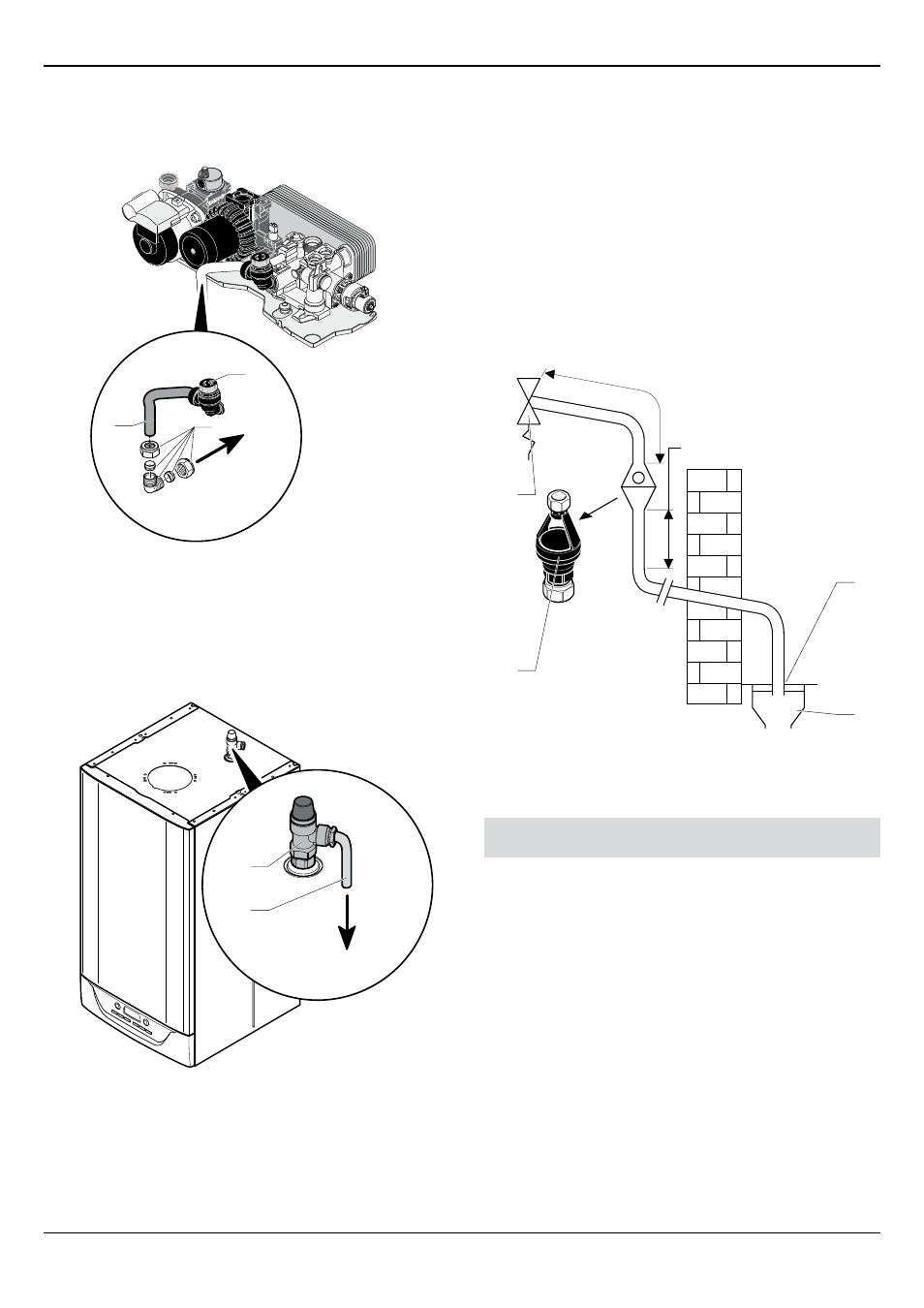
Safety Discharge Valves
8.2.1
Heating safety valve
H
2
1
3
Key
1 Pressure relief valve pipe
2 Heating safety valve
3 Compression fitting
H
Pressure relief valve outlet - to outside
8.2.2
Combined temperature and pressure relief valve
I
2
1
Key
1 Pipe for Pressure relief valve
2 DWH safety valve
I
Pressure relief valve outlet - to outside
• Connect the safety valves. The drain equipment must allow the
water flow to be seen.
This must be extended, using not less than 15mm o.d. pipe,
to discharge, in a visible position, outside the building, facing
downwards, preferably over a drain.
To ease future servicing it is advisable to use a compression type
fitting to extend the safety discharge valve tube.
The pipe must have a continuous fall and be routed to a position
so that any discharge of water, possibly boiling, or steam cannot
create any danger to persons, damage to property or external
electrical components and wiring.
8.2.3
Discharge
D1: 600 mm max.
D2: 300 mm min.
3
4
1
2
Key
1 Tundish
2 Pressure relief valve
3 Trapped gully
4 fixed grating
Combined Temperature and Pressure relief and Expansion Valve
Discharge arrangement
The outlet connections of the temperature and pressure relief
valve must be connected to the tundish privided. The tundish
must be installed with no greater than 600mm of 15mm pipe (D1)
with the tundish fitted in the vertical position. It is permissable
to connect the expansion valve to this pipe if practicable to do
so, by means of a tee piece. If not the expansion valve must be
fitted with a tundish and discharged using the same methods.
The Tundish must be left in a visible position for the user and
in the same space as the boiler and away from any electrical
components.
The pipe connected to the underside of the tundish (D2) must be
vertical for the first 300mm of length before any bend or elbow,
then any horizontal pipework must be installed with a fall of
at least 1 in 200 to its final discharge location. The pipe must
be either metal or other approved safe material (e.g complying
with BS 7921-1 2006). The minimum pipe size is 22mm copper
(or equivilent internal diameter material). To calculate the D2
pipe maximum equivilent length see the table and the worked
example. As an alternative BS 6700:2006 can be used.
INSTALLATION