Installation – Glow-worm Ultracom2 35 Store User Manual
Page 19
0020112185_PROTO_13 - 01/11 - Glow-worm
- 17 -
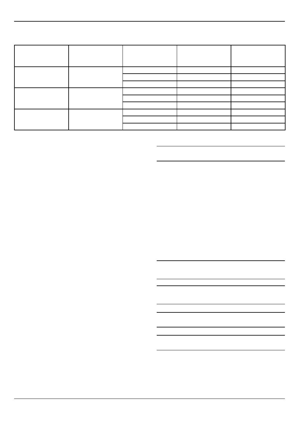
Sizing of copper discharge pipe "D2" for common
temperature relief
Valve outlet size
Minimum size of discharge
pipe D1
Minimum size of discharge
pipe D2 from tundish
Maximum resistance
allowed, expressed as a
length of straight pipe (i.e.
no elbows or bends
Resistance created by each
elbow or bend
G1/2
15mm
22mm
Up to 9m
0.8m
28mm
Up to 18m
1.0m
35mm
Up to 27m
1.4m
G3/4
22mm
22mm
Up to 9m
1.0m
28mm
Up to 18m
1.4m
35mm
Up to 27m
1.7m
G1
28mm
22mm
Up to 9m
1.4m
28mm
Up to 18m
1.7m
35mm
Up to 27m
2.3m
The above table is based on copper tube. Plastic pipes may be
of different bore and resistance. Sizes and maximum lengths of
plastic should be calculated using data prepared for the type of
pipe being used.
Worked example
The product is supplied with a G1/2 T&P valve the pipe D2 is
measured to be 4m in length from the tundish to the point of
discharge with 4 elbows.
7m of 22mm pipe = 4m
4 22mm elbows = 0.8 X 4 = 3.2m
3.2 + 4 = 7.2m and permissable in 22mm pipe should the
calculation not be permissable in 22mm the pipe must be
increased to 28 or even 35mm copper pipe or internal diameter
equivilent.
If in multiple dwellings a common discharge pipe is used it
should be at least one pipe size larger than the largest individual
discharge pipe to be connected.
Connection into soil stacks
Under normal circumstances it is not permissable to discharge
the pipe (D2) into a soil stack unless the following conditions are
met
1. The soil stack and its seals are clearly designed and marked
to withstand the temperatures of the water which could be
discharged under fault conditions.
2. A mecahnical type seal trap is used (water traps are not
permitted) with a temperature rating defined as above
3. It is a separate branch pipe with no other sanitary appliances
connected to it.
4. If the branch pipe used is plastic it must be either
- a. Polybutalene (PB) Class S of BS 7921-2:2006
- b. Cross linked polyethylene (Pe-X) Class S of BS 7921-3:2006
- c. A continuous marking applied to the pipe to warn that no
sanitary appliance may be fitted to it
Termination of the discharge pipe
i
The discharge pipe must terminate in a safe place where
there is no risk to persons in the vicinity of the discharge.
Acceptable terminations are
1. Into a trapped gully, the end of the pipe may be below the
grating but above the water seal
2. Facing downward and up to 100mm above an external surface
(providing a type of wire cage is fitted to prevent contact)
3. Discharged at a high level into a metal hopper and downpipe
(the end of the pipe must be visible)
4. Discharged onto a roof providing that
- a. The roof is constructed of a material designed to withstand
the temperatures
- b. The gutter or drain system connected to the roof is at least
3m away from the point of discharge
b
The tundish should be installed so that is is visible to
the occupants and is positioned away from electrical
devices.
b
The discharge pipes (tundishes) drain valves
etc. shall be positioned away from any electrical
components.
b
Cylinder relief valve connections should not be used
for any other purposes.
b
No valve should be fitted between the expansion
valve and the storage cylinder.
INSTALLATION