Installation, Ab c – Glow-worm Ultracom2 35 Store User Manual
Page 14
0020112185_PROTO_13 - 01/11 - Glow-worm
- 12 -
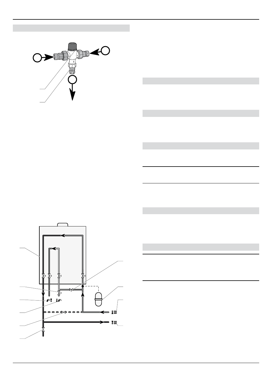
Prevention of scalding - Thermostatic mixing valve
2
1
A
B
C
Key
1 Thermostatic mixing valve
2 Standard flue length horizontal
A Hot water
b Cold water
C Mixed water
A thermostatic mixing valve is used in
the
domestic hot water
circuit.
It’s function is to maintain the temperature of the mixed water,
supplied to the user, constant at the set value when there
are variations in the supply pressure and temperature of the
incoming hot and cold water or in the flow rate.
The hot water supply temperature to a bath should be limited to
a maximum of 48°C. The thermostatic mixing valve should not be
easily altered by users.
The thermostatic mixing valve conforming to WRAS,
BS EN
1111
and
BS EN
1287, compliant to Part G of the bluiding regulations.
7.2.2
Heating circuit design
6
4
5
3
2
1
8
7
9
10
Key
1 Drain point
2 External bypass (if required)
3 Domestic cold water supply in
4 Domestic hot water out
5 Pressure reducing valve (if required)
6 boiler
7 filling loop in accessory box
8 Additional expansion vessel (if required)
9 Heating return circuit
10 Heating flow circuit
General
This boiler is designed for use as part of a sealed water central
heating system with fully pumped circulation. The pump,
expansion vessel and associated safety devices are all fitted
within the boiler.
Safety valve
The safety valve is an integral part of the boiler and it cannot
be adjusted. The pipe from the safety discharge valve must
discharge safely in accordance with standards.
Expansion vessel
The boiler has an integral expansion vessel with a capacity of 12
litres (2.64 gallons), with a charge pressure of 0.75bar.
i
The heating system volume should be calculated to
ensure that the expansion vessel is suitable, it may be
necessary to add an additional vessel.
- In GB, Guidance on vessel sizing is also given in the current
issue of BS5449 and BS7074 Part 1.
- In IE, current edition of I.S.813 “Domestic Gas Installations”
.
Bypass
The boiler is fitted with an automatic bypass which can be
adjusted to suit your system requirements.
• Ensure that under no circumstances does the flow rate drop
below the figure specified, refer to chapter "Technical data".
Filling the sealed system
i
The water pressure at the boiler must be at least
1.2bar to operate the filling loop. If the pressure is
less than 1.2bar an external filling loop must be fitted.
If this pressure is not available contact the local water
authority.
Suitable external filling systems are shown diagrammatically, see
diagram
overleaf
.
INSTALLATION