Maintenance, Ab b – Glow-worm Ultracom2 35 Store User Manual
Page 46
0020112185_PROTO_13 - 01/11 - Glow-worm
- 44 -
18.2 Casing removing
18.2.1
front panel
A
B
A
2
1
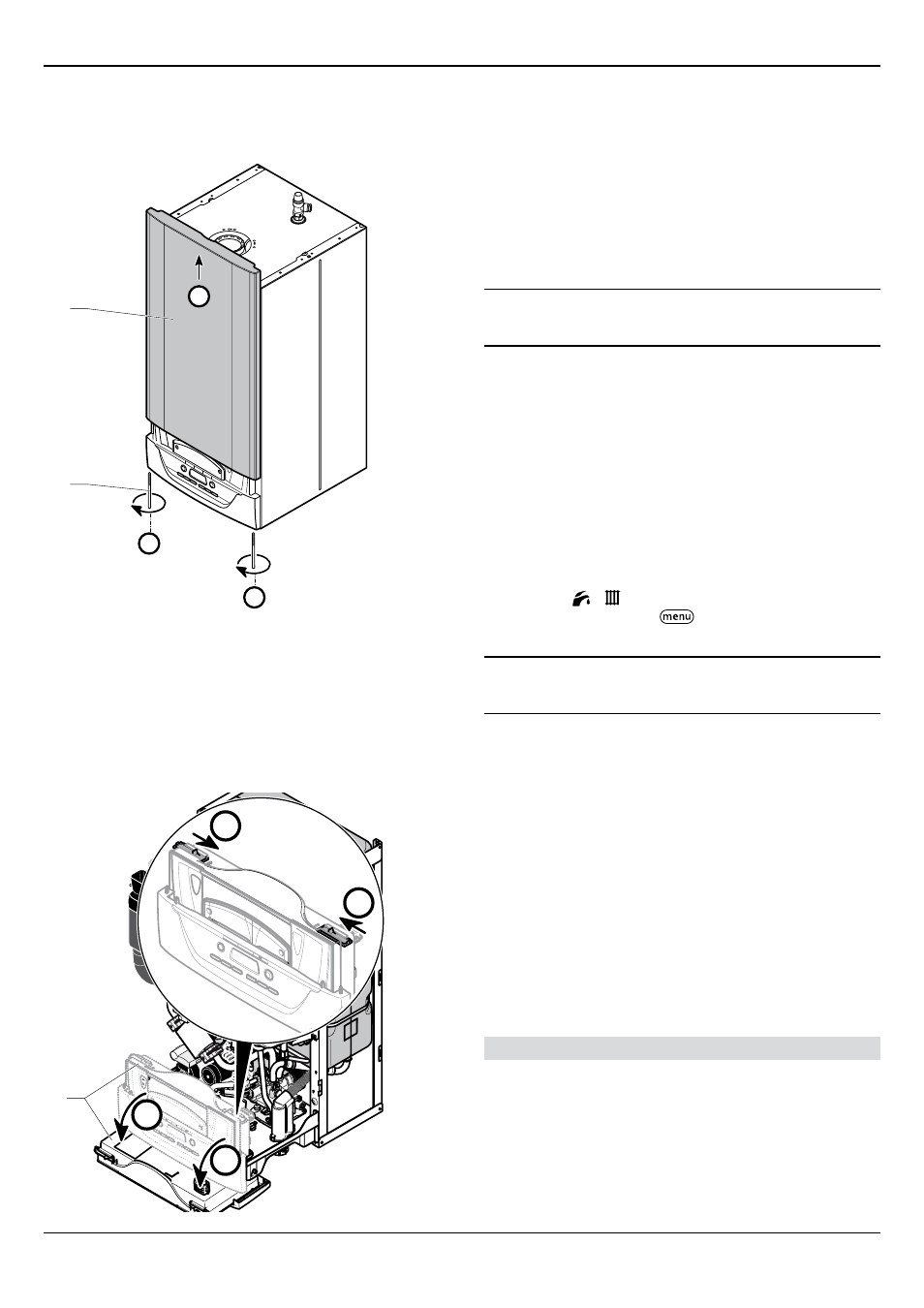
Key
1 front panel retaining screw
2 front panel
• Undo the two screws (1) on the underside of the front panel
and remove the front panel (2).
18.2.2
Control box
230
V
230
V
A
A
B
B
1
Key
1 Control box
• Position the control box (1) into the service position.
18.3 Combustion check and setting the air/gas
ratio valve
18.3.1
Competency to carry out the check of
combustion performance
i
BS 6798: 2009 Specification for installation and
maintenance of gas-fired boilers of rated input not
exceeding 70kW net advises that:
- The person carrying out a combustion measurement must be
assessed as competent in the use of a flue gas analyser and
the interpretation of the results.
- The flue gas analyser used should be one meeting the
requirements of BS7927 or BS-EN50379-3 and be calibrated in
accordance with the analyser manufacturers’ requirements.
- Competence can be demonstrated by satisfactory completion
of the CPA1 ACS assessment, which covers the use of
electronic portable combustion gas analysers in accordance
with BS 7967, parts 1 to 4.
• Ensure that the gas analyser is set to the correct fuel
setting.
• Select the “ + ”, constant central heating with DHW
function by pressing the “
” button repeatedly, refer to
commissioning section. The boiler should fire automatically.
i
Safe combustion can only be verified by measuring
CO/CO
2
ratio. This must not exceed the value shown in
the table opposite.
18.3.2
Preliminaries
Prior to, during servicing and after any maintenance or changed
parts, the following must be checked.
• The integrity of the flue system and flue seals.
• The integrity of the appliance combustion circuit and relevant
seals.
• Electrical, gas and water connections.
• System pressure.
• The combustion performance, refer to the following procedure.
• The operational gas inlet pressure and gas rates, refer to the
commissioning section paragraph 12.5. Correct any falt before
continuing.
Combustion check and setting the air/gas ratio
• Remove the front casing panel, see diagram above and hinge
down the control box. Taking care not to touch any internal
components, proceed as follows:
• Connect the CO
2
combustion analyser to the relevant test
point, see diagram opposite.
MAINTENANCE