Installation – Glow-worm Ultracom2 35 Store User Manual
Page 27
0020112185_PROTO_13 - 01/11 - Glow-worm
- 25 -
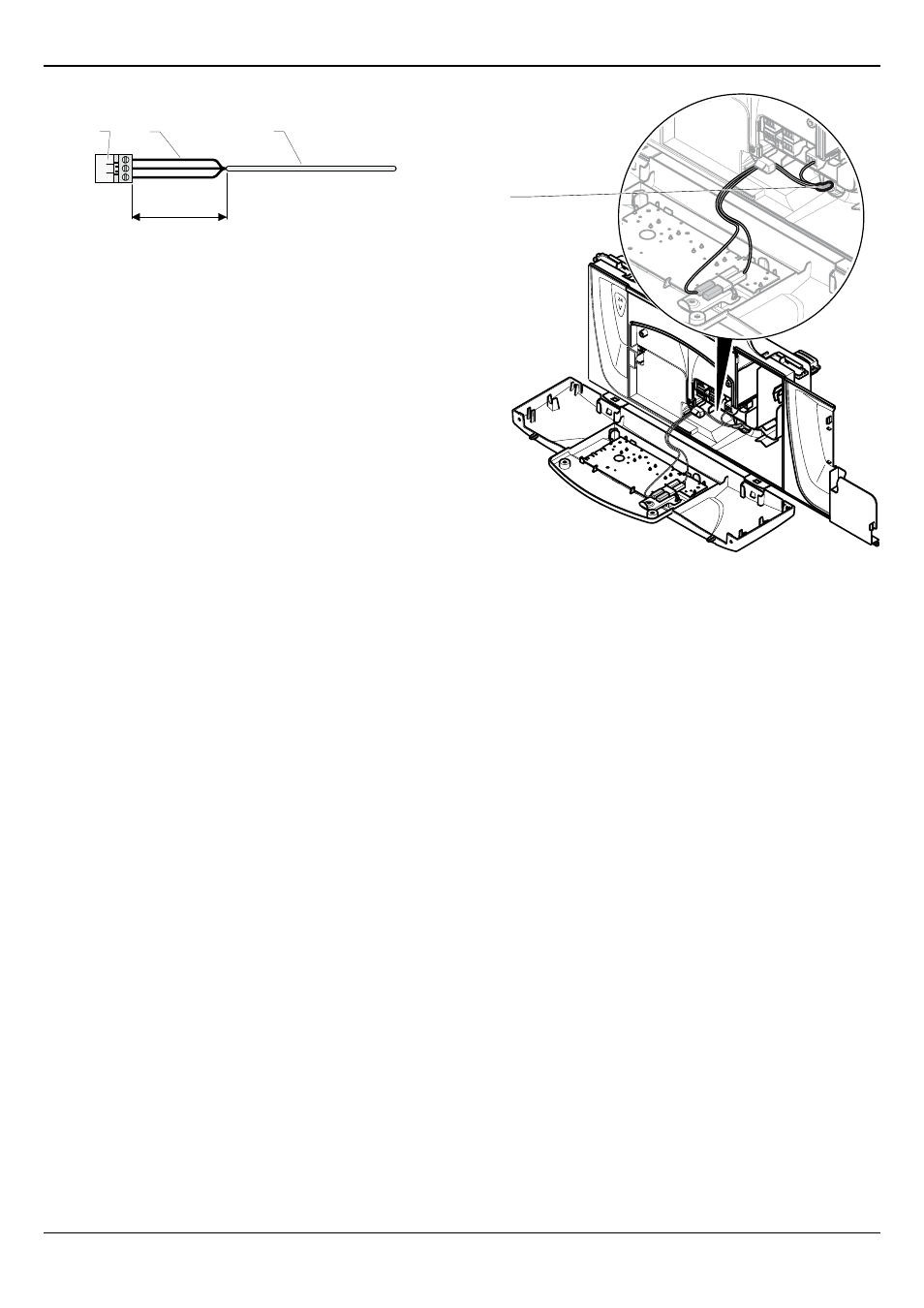
11.2 Main board
1
2
3
30 mm max.
Key
1 Connector
2 Electrical wires
3 Insulation
When you connect the electrical wires to a connector on the
electronic board:
• Keep a distance of a maximum of 30 mm between connector
(1) and the start of the insulation (3).
• If using single core wires are used(2) ensure that the are
wrapped together in an insulating sheath.
• Fix the cables in the cable-clamp on the eBox.
11.3 Electrical wiring
Connection of the whole electrical system and any heating system
controls to the electrical supply must be through a common
isolator.
Isolation should preferably be by a double pole switched fused
spur box having a minimum contact separation of 3mm on
each pole. The fused spur box should be readily accessible and
preferably adjacent to the boiler. It should be identified as to its
use.
A fused three pin plug and shuttered socket outlet may be used
instead of a fused spur box provided that it is not used in a room
containing a fixed bath or shower.
1
Key
1 Power supply cable
• Connect the appliance's power cable to the 230 V single-phase
network + earth.
• Connect the appliance in accordance with the live and neutral
connections.
INSTALLATION