Note, C. reassembly, Engine – Bolens 132-395A User Manual
Page 17: Belt replacement, Warning, Blade belt (see figure 32), Transmission belt (see figure 31)
Attention! The text in this document has been recognized automatically. To view the original document, you can use the "Original mode".
When sharpening the blade, follow the original
angle of grind as a guide. It is extremely important
that each cutting edge receives an equal amount
of grinding to prevent an unbalanced blade. An un
balanced blade will cause excessive vibration
when rotating at high speeds, may cause damage
to the mower and could break, causing personal
injury.
The blade can be tested for balance by balancing
it on a round shaft screwdriver. Remove metal
from the heavy side until it balances evenly.
NOTE
It is recommended that the blade
always be removed from the adapter
for the best test of balance.
C. Reassembly
Before reassembling the blade and the blade
adapter to the unit, lubricate the spindle and the
inner surface of the blade adapter with light oil.
Lubricating the bolt holes, bolts and inner surface
of the nuts with light oil is also recommended. A 4
oz. plastic bottle of light oil lubricant is available.
Order part number 737-0170. Engine oil may also
be used.
When replacing the blade, be sure to install the
blade with the side of the blade marked “Bottom”
(or with part number) facing the ground when the
mower is in the operating position. Make certain
key is in place on the crankshaft.
Blade Mounting Torque
3/8" Dia. Bolt 375 in. lb. min., 450 in. lb. max.
5/16" Dia. Bolt 150 in. lb. min., 250 in. lb. max.
To insure safe operation of your unit, ALL nuts
and bolts must be checked periodically for correct
tightness.
Disconnect the spark plug wire and ground it
against the engine.
To prevent gasoline from leaking from the gaso
line tank, remove the cap, place a piece of plastic
film over the neck of the tank, screw on the cap, or
drain tank.
1. Put the lift lever in the disengaged position.
2. Remove the belt keeper and shoulder bolt on
the engine pulley. See figure 30.
/1- )
Belt Keeper
Bolt
FIGURE 30.
3. Remove the blade belt from the engine pulley.
4. Put the lift lever in the engaged position.
5. Remove the two tension springs on the rear of
the deck.
6. Remove the six pins holding the deck to the
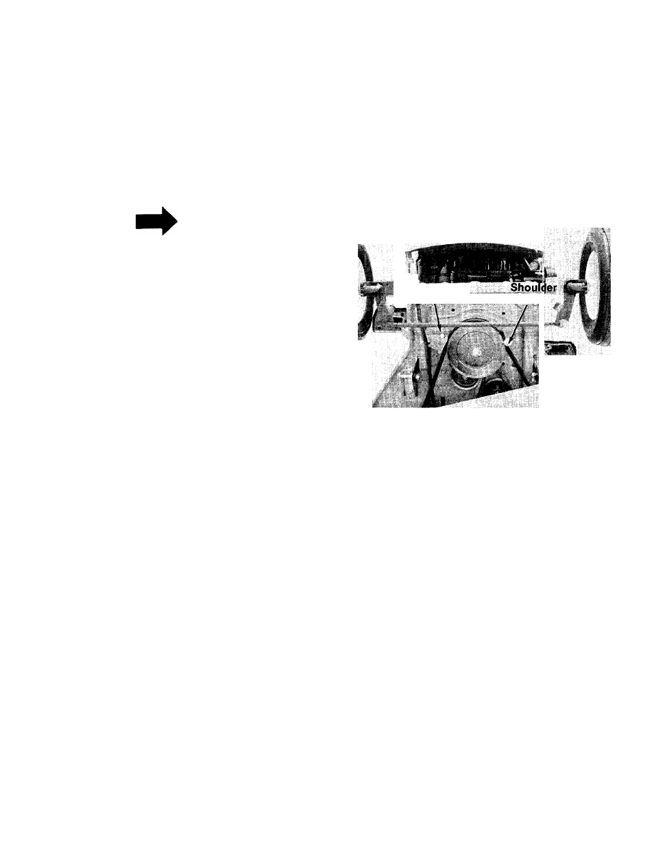
frame. See figure 31.
7. Lift off the deck and set it aside.
ENGINE
Refer to separate engine manual for maintenance
procedures.
BELT REPLACEMENT
^ WARNING \
Before
up-ending
vehicle
for
maintenance, position it on a hard
level surface. Make sure area is
clear of children and pets. Secure
(tie) in place.
BLADE BELT (See figure 32)
1. Take off both belt guards on the deck.
2. Remove and replace the belt with a new one.
TRANSMISSION BELT (See figure 31)
1. Remove the engine belt guard from the engine
pulley by removing the two front engine bolts.
2. Remove the two belt guards from the
transmission pulley.
3. Remove the V-idler pulley.
4. Remove and replace the transmission belt
and reinstall pulley.
17