Throttle control, Ignition key, Interlocks (not shown) – Bolens 132-395A User Manual
Page 11: Brake, Brake lock, Clutch, Clutch lock, Controls
Attention! The text in this document has been recognized automatically. To view the original document, you can use the "Original mode".
CONTROLS
(See Figure 17)
This manual should be read in its entirety before
operating the lawn tractor. The more you know
and understand about the machine and its opera
tion, the better job it wili do for you. While reading
the manual, compare the illustrations with your
tractor to familiarize yourself with the locations of
various controls, lubrication points, attachments
and adjustment features.
Study the operating instructions and safety
precautions thoroughly to insure proper function
ing of your tractor and to prevent injury to yourself
and others. Be sure to save this manual for future
reference.
THROTTLE CONTROL
The throttle control is used to regulate the engine
speed and to activate the choke on the engine. To
get maximum efficiency from cutting, the throttle
should be in the FAST position when operating
the mower. Pushing the throttle all the way for
ward past FAST, will choke the engine. See figure
17.
IGNITION KEY
Recoil Model. The key must be turned to the “ON”
position before you pull the recoil handle to start
the engine. Turn the key to the left to the “OFF”
position to stop the engine. Remove the key when
the unit is not in use. See figure 20.
Electric Start Model. The key must be turned to
the “START” position to start the engine. After
the engine is running, let the key return to the
“ON” position. Turn the key to the “OFF” position
to stop the engine. Remove the key when the
mower is not in use. See figure 17.
ThrottI
Contro
INTERLOCKS (Not Shown)
Interlock safety switches are loceited on the
clutch pedal, the lift and disengagement lever and
gear shift lever.
Before the engine will start, the clutch pedal must
be depressed all the way and the lift and
disengagement lever must be in the disengaged
position.
Before the unit can be shifted into reverse, the lift
and disengagement must be in the disengaged
position.
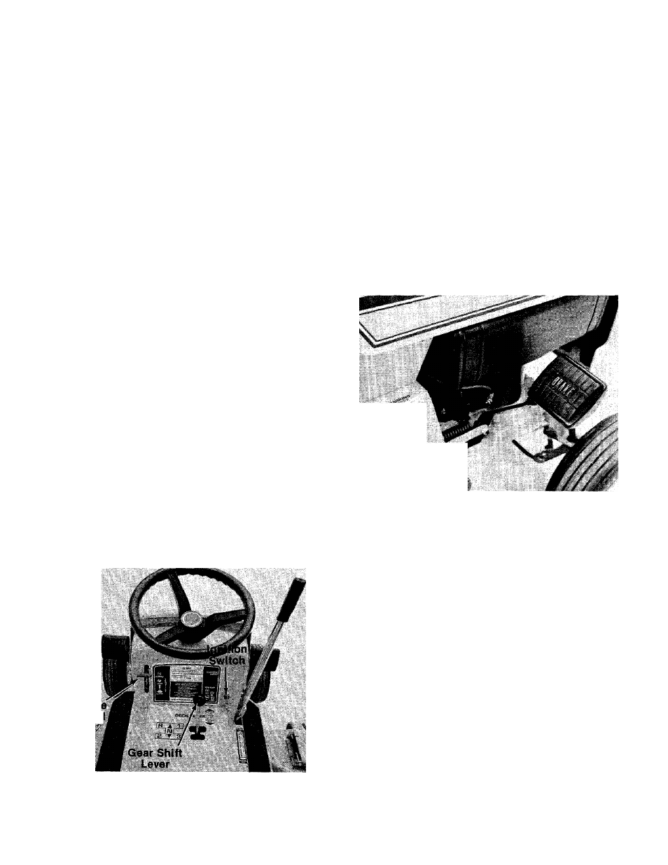
BRAKE
The brake pedal is located on the right hand side
of the tractor and is operated by depressing it with
your right foot. See figure 18.
,
(piown Locked)
FIGURE 17.
FIGURE 18.
BRAKE LOCK
The brake lock is located on the right hand side of
the tractor. To lock the brake, depress the brake
pedal and lift up the lock button. The pedal will
stay depressed. To release, depress the brake
pedal. Always lock the brake when you park the
mower. See figure 18.
CLUTCH
The clutch pedal is located on the left hand side of
the tractor and is operated with your left foot.
Depress the pedal to disengage the drive
mechanism. Release the clutch slowly to engage.
The clutch and brake pedals must both be
depressed when stopping the tractor. When shift
ing gears, the clutch pedal must be disengaged,
and the tractor cannot be moving. See figure 19.
CLUTCH LOCK
When the clutch pedal is depressed all the way, it
can be locked by lifting up the lock button. The
pedal will stay depressed. To release, depress the
pedal. See figure 19.
11