Height of cut controls, Setting the cutting height, Caution – Bolens 132-395A User Manual
Page 13: Starting the engine, Warning, Operation
Attention! The text in this document has been recognized automatically. To view the original document, you can use the "Original mode".
HEIGHT OF CUT CONTROLS
The cutting controls consist of the height of cut
stop and the wheel height adjusters.
Height of Cut Stop. See figure 22. Lift the stop and
set it at the desired cutting height. Allow the lift
and disengagement lever to come forward to rest
against the height of cut stop.
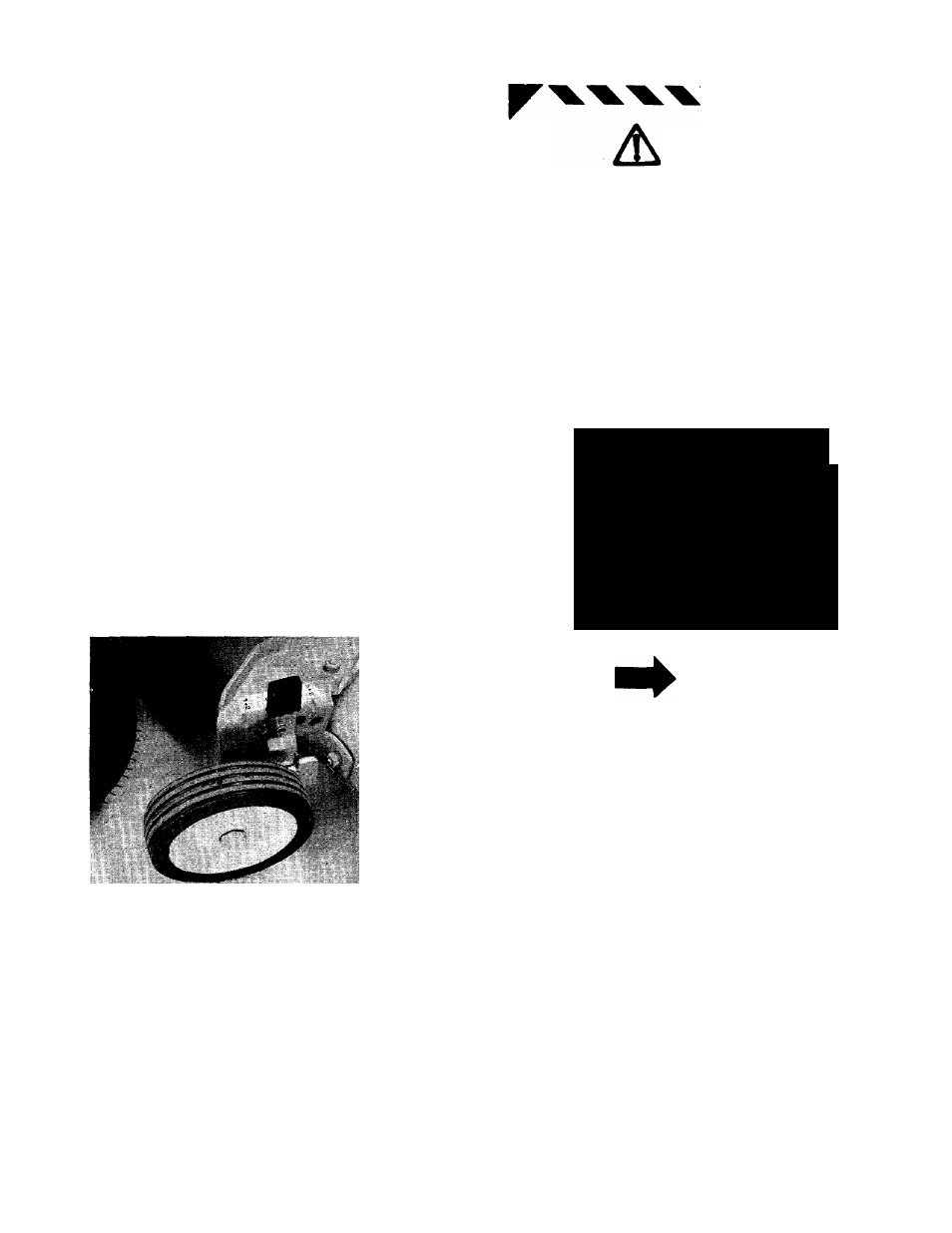
Wheel Height Adjuster. Move the lever towards
the wheel and set it in the desired cutting height
position. See figure 23. Both wheels must be in
the same relative position.
SETTING THE CUTTING HEIGHT
The cutting height of the mower can be set in two
different ways: Full Float position where the deck
follows the contour of the ground, and the
Suspended position where the deck hangs from
the frame of the rider. The suspended position is
normally used for cutting rough uneven ground.
To set the cutting deck in the full float position:
Set the wheel height adjusters in the desired cut
ting height as indicated in figure 23. Set height of
cut stop in the lowest position. See figure 22.
To set the cutting deck in the suspended position:
Set the height of cut stop in the desired cutting
height. Then set the deck wheels so they just
clear the ground.
FIGURE 23.
OPERATION
For shipping purposes, the tires on your unit may
be over-inflated. Tire pressure should be reduced
before unit is put into operation. Recommended
pressure should be approximately 15 p.s.i. Equal
tire pressure should be maintained on all tires.
Maximum tire pressure is 30 p.s.i.
4
4
4
\
CAUTION
Keep all shields in place.
Before leaving operator’s position:
a. Shift transmission to neutral
b. Set parking brake
c. Disengage attachment clutch
d. Shutoff engine
e. Remove ignition key
Wait for all movement to stop before
servicing machine.
Keep people and pets a safe distance
away from machine.
Look to the rear before backing up.
CAUTION
DO
NOT
OPERATE
M O W E R
U N L E S S
GUARD DR ENTIRE
GRASS CATCHER IS
IN ITS PROPER PLACE.
STARTING THE ENGINE
NOTE
This unit is equipped with a safety
interlock system for your pro
tection. The purpose of the safety
interiock system is to prevent the
engine from cranking or starting
unless the clutch pedal is de
pressed and the lift and disen
gagement lever is in the disengaged
position. In addition, the lift and
disengagement lever must be in the
disengaged position when the unit
is put into reverse or the engine will
shut off.
4
4
\
4
4
A
WARNING
i
1
.
Do not operate the rider if the inter
lock system is malfunctioning be
cause it is a safety device, designed
for protection.
Be sure the crankcase is filled with oil as
recommended in the engine manual. Put
regular gasoline in the gasoline tank.
13