Operation – Ariens 929001 User Manual
Page 6
Attention! The text in this document has been recognized automatically. To view the original document, you can use the "Original mode".
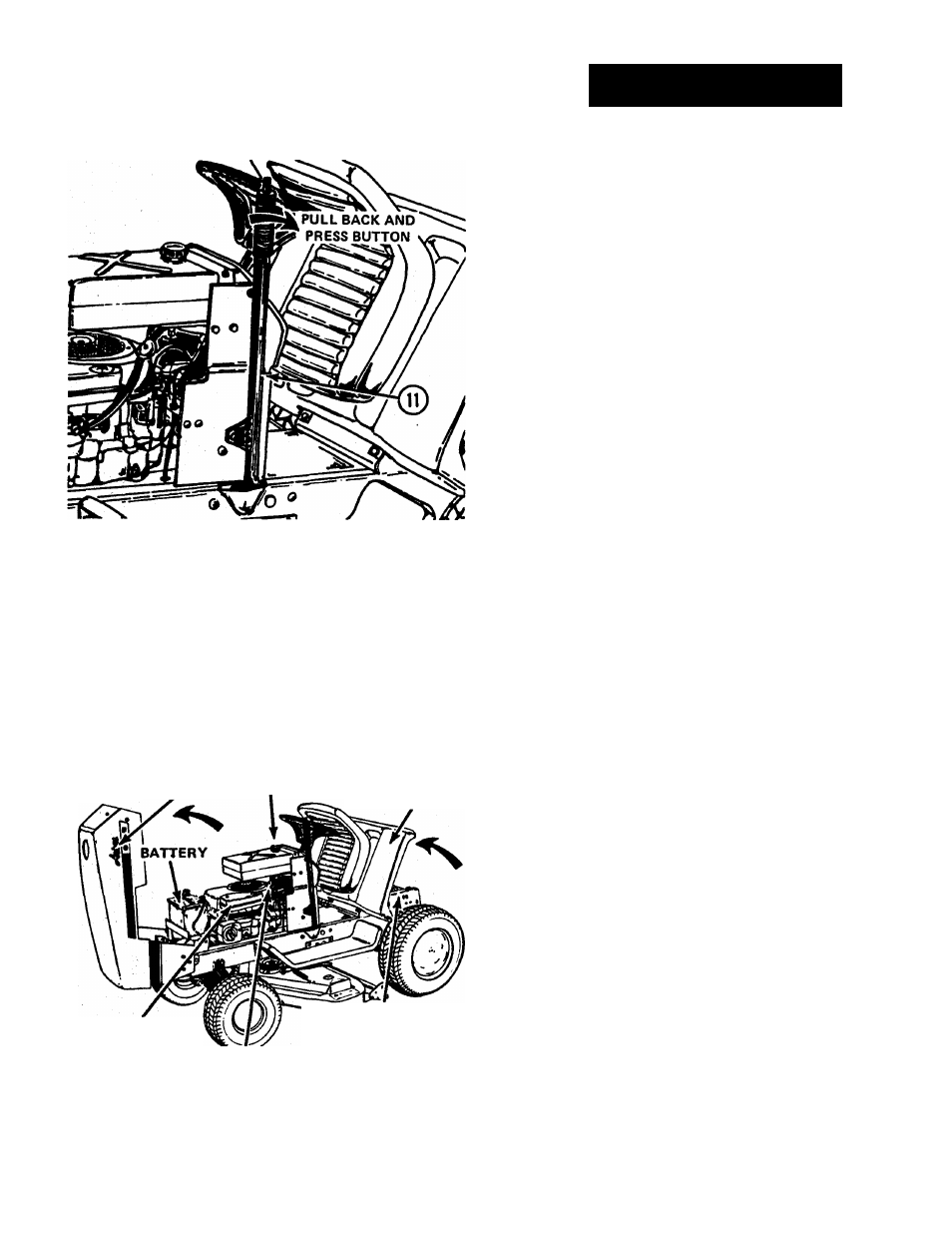
To lower the attachment, pull the lever to the rear, de
press the button to release the latch and allow the lever to
move forward. See Figure 7.
Figure 7
RAISING THE HOOD-iFigure 8)
The engine, battery, electrical components, air cleaner, fuel
filter and fuel tank are readily accessible by raising the hood.
To raise the hood, grasp each side and raise it upwards and
forward to its stop.
RAISING THE REAR DECK - (Figure 8)
The differential, transmission and control linkages are
readily accessible by raising the rear deck until the seat rests
against the steering wheel.
LIFT UP
HOOD
FUEL
TANK
FILLER CAP
LIFT UP
REAR DECK
AIR CLEANER
TRANSMISSION
AND
DIFFERENTIAL AREA
FUEL FILTER
Figure 8
OPERATION
PRE-STARTING INSPECTION
Before starting the engine before each day's operation, t
following checks and services should be performed:
1. Check oil in engine crankcase. Add oil as required to main
tain proper level. See lubrication section.
2. Check fuel supply. Fill with clean, fresh regular gasoline
only. See lubrication section.
3. Check air cleaner and service as required.
4. Check for engine, transmission or differential oil leaks. See
your authorized Ariens dealer for repairs.
5. Make visual checks regarding safety precautions, ob
structions and maintenance.
STARTING THE ENGINE
Use the following procedure to start the engine:
1. Lock the parking brake^^y depressing the foot pedal
Figure 4, and pushing the brake lock forward to lock the
parking brake.
2. HYI
. ©
YDROSTATIC MODELS. Place hydrostatic control lever
in the "park-start" position as shown in Figure 2.
NOTE: The engine will not start unless the control lever is in
the "park-start" position.
^3. GEAR SHIFT MODELS. Place gear shift lever(3)i
forward (neutral) position as shown in Figure 3.
in tl
NOTE: The engine will not start unless the gear shift lever is in
the "forward" neutral position.
4. Place implement power clutch lever^T^igure 1, in the rear
(disengaged) position.
NOTE: This is a safety feature. The engine will not start unless
the clutch lever is in the disengaged position.
5. Raise throttle choke control lever^^Figure 6, past the
offset in the slot to the "choke" position.
6. Turn ignition key^^hown in Figure 6 clockwise aH the
way. Release key as soon as the engine starts and
gradually lower the throttle-choke control lever past the
offset until the engine runs at 'A throttle.
NOTE: A WARM ENGINE WILL REQUIRE LESS CHOK
ING THAN A COLD ENGINE.
If the engine fails to start on the first attempt, turn key
to the "off" position, wait a few minutes and try again. Do
not operate starter continuously for more than 30 seconds at
a time.
Always allow engine to warm up before applying load,
below freezing weather, allow engine to run at a fast idu.
for a period of at least five minutes before moving the
Pages