Ariens 929001 User Manual
Page 16
Attention! The text in this document has been recognized automatically. To view the original document, you can use the "Original mode".
HYDROSTATIC CONTROL LEVER BRAKE ADJUSTMENT
BELT REPLACEMENT
The hydrostatic control lever friction brake must be ad
justed so the control lever moves through the "forward" and
"reverse" modes with a minimum of force. However, due to
the neutral tendency of a hydrostatic transmission to neu
tralize. the brake must be tightened sufficiently so the trac
tor maintains any selected speed setting.
To adjust the friction brake, tighten or loosen bolt D,
Figure 33, until the proper braking is reached.
FRONT WHEEL TOE-IN ADJUSTMENT
Proper toe-in of the front wheels is necessary to assure
proper steering and to reduce tire wear. Correct toe-in is
when the front of the wheels are 1/8" to 1/16" closer together
than the rear of the wheels (measured at the horizontal
center line of the rim flanges).
If the steering develops a wandering characteristic or if
excessive tire wear develops, the toe-in of the front wheels
should be checked. If the toe-in is not correct, adjust as
follows:
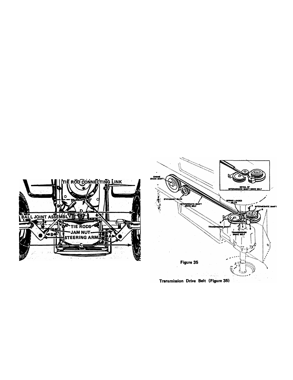
1. Turn steering wheel until the rear edge of the tie rod
connecting link is perpendicular (90 degrees) to the
tractor frame as shown in Figure 34.
2. Adjust length of tie rods until distances A and B are equal
and so distance C is between 1/8" to 1/16" less than
distance D.
Figure 34
NOTE: Use following procedure to shorten or lengthen
tie rods:
-
1. Loosen jam nuts on both ends of tie rods. Figure 34.
2. Rotate tie rods until distances A and B, Figure 34, are
equal and distance C is 1/8" to 1/16" less than 0.
3. Tighten jam nuts securely.
SEAT ADJUSTMENT
The seat is adjustable front or back to any one of six dif
ferent positions. Adjustment is made by removing the four
mounting bolts located under the seat, moving the seat to the
most comfortable position and then replacing the mounting
bolts in the appropriate holes.
If it becomes necessary to replace one of the tractor
drive belts, the following diagrams show the proper place
ment of the belts and belt guides. After installing a belt it
will be necessary to follow the adjustment procedures out
lined in the ADJUSTMENT section of this manual.
PTO DRIVE BELT - (Figure 32)
1. Adjust guide A to clear the engine drive sheave by 1/8 inch.
2. Adjust guide G to clear the floating jackshaft sheave by
1/8 inch.
3. Position idler F to provide least amount of belt tension
when instaiiing a new belt.
4. Adjust belt tension and guides D and E using the procedure
outiined in "Maintenance and Adjustment" section.
MECHANICAL TRANSMISSION DRIVE BELTS -
(Figure 35)
Intermediate Shaft Drive Belt
Follow the instructions outlined in the ADJUSTMENT
section.
Page 16
1. Position guides A and B 1/8" from drive sheave at the
points where belt is tangent to the sheave.
2. Position guide D, 1/8" from the transmission sheave.
3. Idler E is mounted in a slotted hole. Position to provide
least amount of belt tension when installing a new belt.
4. Place guide C 1/8" from the belt in such a position thatjt
does not bind the belt in any position of the idler.
5. Adjust belt tension using the procedure outlined in
ADJUSTMENT section.