Controls – Ariens 929001 User Manual
Page 4
Attention! The text in this document has been recognized automatically. To view the original document, you can use the "Original mode".
CONTROLS
©
IMPLEMENT POWER CLUTCH - Figure 1
The implement power clutch is used to operate the
mower or snow thrower. Push the lever forward to
engage the clutch and drive the attachment. Pull the lever
rearward to disengage the clutch and stop the attachment.
The lever must be in the rear (disengaged) position to start
the engine. THIS IS A SAFETY FEATURE. The engine will
not start until the lever has been placed in the disengaged
position.
Figure 1
©
HYDROSTATIC
CONTROL
LEVER
(Hydrostatic Models — Figure 2
This lever regulates both tractor speed and direction.
Gradually move the lever forward from the "park-start" (neu
tral) position to increase forward travel speed. Move the
lever rearward to the "R" position to back the tractor and
regulate reverse speed.
NOTE: The lines and numbers next to the forward slot do
not indicate a given speed. They serve as guide lines only.
Figure 2
THE CONTROL LEVER MUST BE IN THE "PARK-START"
POSITION TO START THE ENGINE.
©
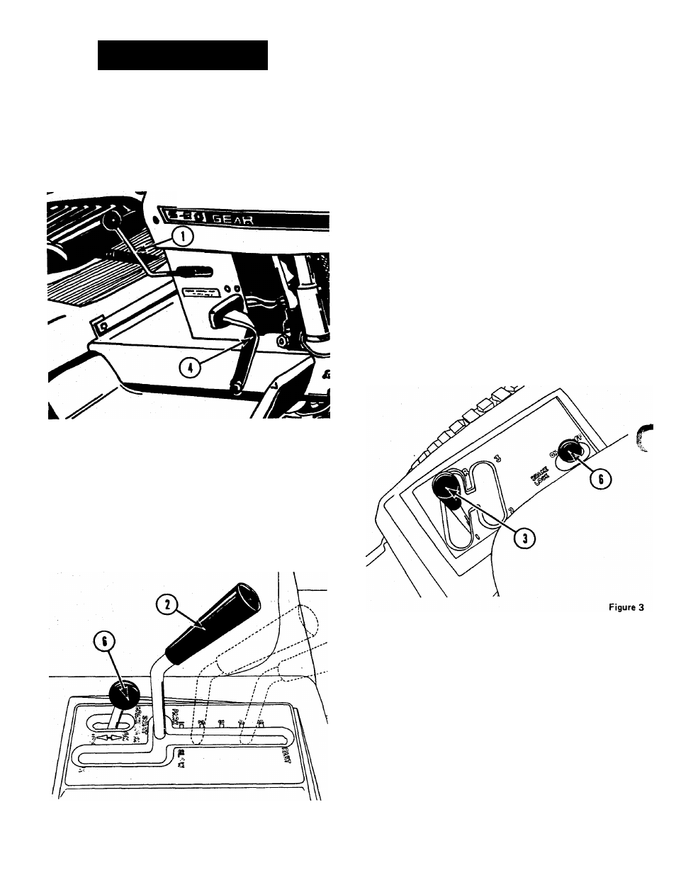
GEAR SHIFT LEVER - (Gear Shift Models) -
Figure 3.
The gear shift lever is used to select any of three 1
forward gears or one reverse gear. The markings 1, 2, 3 and
R on the control console indicate the locations of the gears.
The slowest forward gear is indicated by No. 1, the secondary
gear, No. 2 and the fastest gear. No. 3. The "R" indicates
reverse.
THE GEAR SHIFT LEVER MUST BE IN THE FORWARD
NEUTRAL POSITION AS SHOWN IN FIGURE 3 TO START
THE ENGINE.
©
HYDROSTATIC
NEUTRALIZER
AND
BRAKE
PEDAL (Hydrostatic Models) — Figure 1
. When this pedal is depressed, the hydrostatic control
lever will return to neutral and stop the forward or reverse
motion of the tractor. At the same time, the pedal actuates
an independent brake which provides an additional means of
stopping the tractor.
NOTE:
ALWAYS
REMOVE
HAND
FROM
HYDROSTATIC
CONTROL
LEVER
BEFORE
DEPRESSING
THE
NEU
TRALIZER
AND
BRAKE
PEDAL
THE
TWO CONTROLS
ARE
INTERCONNECTED.
OPERATING
THEM
SIMUL
TANEOUSLY
COULD
RESULT
IN
DAMAGED
OR
MIS-
ADJUSTED LINKAGE.
©
CLUTCH BRAKE PEDAL (Gear Shift Models) -
Figure 4
The clutch-brake pedal performs two functions:
1. When depressed to the "midway" range the clutch dis
engages and the transmission can be shifted to any desired
gear.
2. When the clutch-brake pedal is fully depressed, the brake
actuates and stops the tractor.
NOTE: Always release the pedal slowly for smooth ac
celeration. Do not allow foot to rest on pedal except for ^
clutching and braking functions.
Page 4