Auger/impeller – Ariens 924 User Manual
Page 46
Attention! The text in this document has been recognized automatically. To view the original document, you can use the "Original mode".
Auger/Impeller
7.1 Introduction
A
WARNING: Remove wire from spark plug
before attempting any repair or adjustment
procedures.
When unit is tipped to preform the service proce
dures in this section, remove enough fuel so that no
spillage will occur, block securely and remove bot
tom cover.
Grasp auger assembly and pull gear case and auger/
impeller assembly free of housing.
Drive roll pin out of shaft ends, remove shear bolts
and remove auger from shaft.
Check all parts for wear or replacement.
Assemble using reverse procedure.
A
WARNING: Gasoline is highly flammable
and its vapors are explosive. Handle with
care.
7.4 Attachment Clutch/Impeller Brake
7.2 Auger/Impeller Housing
To separate housing from unit, remove two screws
securing belt guard to unit and remove belt guard.
Remove hairpin from chute crank assembly at "U"
joint and separate.
Remove attachment drive belt from engine pulley
(it may be necessary to turn engine pulley using
rewind starter).
IMPORTANT: To avoid bending bottom cover,
when tipping unit apart, support handlebars firmly
or tip unit up on housing and remove bottom cover
by removing four cap screws before separating
unit.
Remove cap screws securing housing to frame (one
on each side). Tip housing and frame apart on pivot
pin.
7.3 Auger/Impeller Removal
Remove (3) three nuts holding pulley to hub and re
move pulley and key.
Loosen set screw in hub and remove hub.
Remove (3) three nuts holding bearing flange to
housing and remove bearing flange.
Remove (2) two cap screws and lockwashers on each
side of blower housing holding rake shaft in position
and remove bushing.
Remove (3) three lock nuts attaching bearing
support to housing and remove bearing support.
A
WARNING: With improper use injury may
result if attachment clutch lever is released
and brake DOES NOT STOP auger/impeller
within 5 seconds.
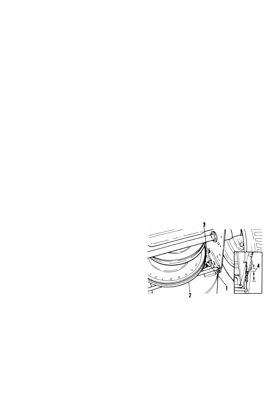
To check and/or adjust impeller brake, tip unit
forward onto auger/impeller housing. Remove bot
tom cover by removing four cap screws. Measure
distance between impeller brake shoe and belt with
attachment clutch engaged. When attachment clutch
is disengaged, brake must contact belt.
1. Brake Shoe
2. Drive Belt
3. 1/16" -1/8" Between Shoe and Belt
4. Spring Extension - 3/8"
Figure 7-3: Impeller Brake
7-4