Carrier 50LJ User Manual
Page 9
Attention! The text in this document has been recognized automatically. To view the original document, you can use the "Original mode".
UNIT SIZE
WEIGHT*
A
B
C
D
E
F
G
Lb
Kg
mm
Ft-in.
mm
Ft-in.
mm
Ft-in.
mm
Ft-in.
mm
Ft-in.
mm
Ft-in.
mm
Ft-in.
48LJD024
2895
1313.0
1813
6-1%
2182
7-1%
682
2-2%
3909
12-9%
534
1-9
2187
7-2%4
807
2-7%
48LJE024
2975
1349.4
1813
6-1%
2182
7-1%
682
2-2%
3909
12-9%
534
1-9
2187
7-2%4
807
2-7%
‘See note 9.
NOTES:
1 Dimensions in [
2
.
are in miilimeters
Center of gravity.
3 Ailow 12'-0" [3658] at top and 6'-0" [1829] on sides for service and op-
erationai clearance.
4. On multiunit applications allow 12'-0" [3658] between adjacent condens
ers and economizers.
5. For smaller service and operational clearances, contact Carrier Appli
cation Engineering Department.
6. Vertical discharge ducts are designed to be attached to accessory roof
curb. If unit is mounted on dunnage, it is recommended the ducts be
supported by cross braces as done on the accessory roof curb.
7 Always line up condenser end of unit tight against the roof curb.
8. Units with power exhaust require a 90 degree elbow in return air duct.
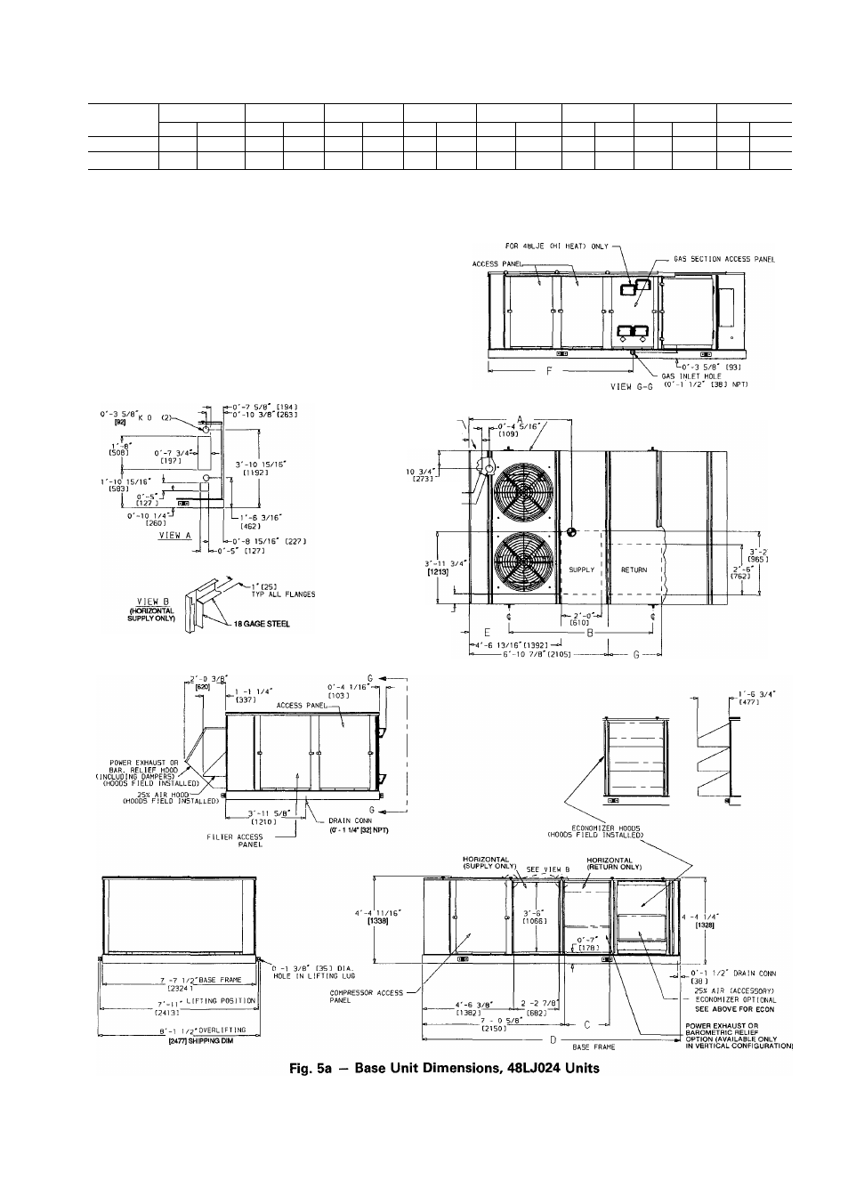
9. Weight of unit includes optional economizer. For unit without econo
mizer, deduct 130 lb (59 Kg).
POWER IN (SIDE).
(SEE VIEW A)
0'-7 13/16:
[
199
]
/—CONTROL BOX ACCESS DOOR
0'-3/4'
0'-3 1/2'
[13] NPT LOW VOLTASE
[89] NPT FIELD POWER
0'-5 13/16'
[146]