Operating sequences – Carrier 50LJ User Manual
Page 23
Attention! The text in this document has been recognized automatically. To view the original document, you can use the "Original mode".
Economizer Dampers and Potentiometer Set
tings
— With no power to the unit, the economizer outdoor-
air dampers should be fully closed. Check by opening
the access door marked FILTER SECTION. On units with
economizer, be sure MAT and economizer minimum posi
tions are set at the desired settings. Be sure hood is in
stalled properly.
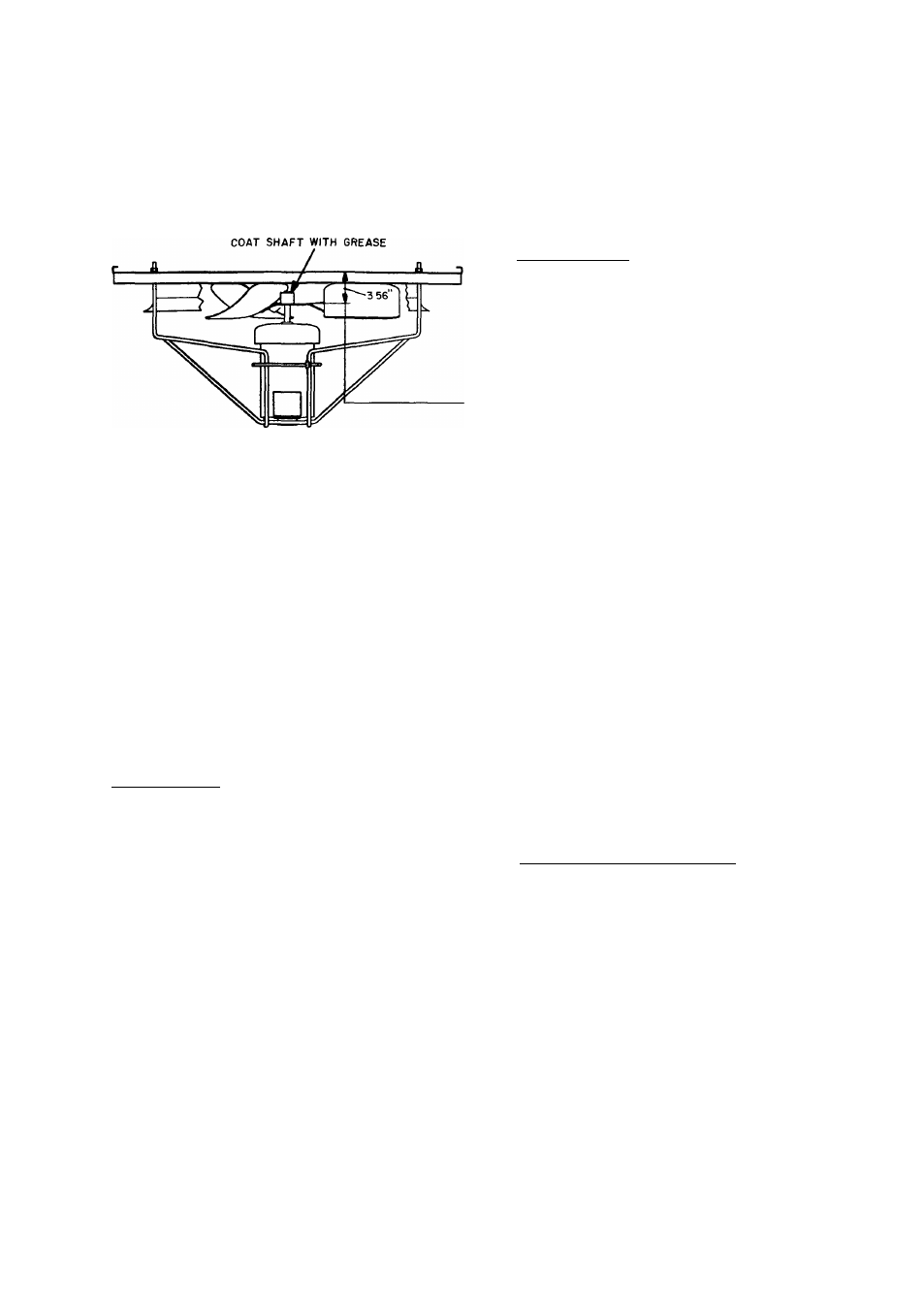
Fig. 20 — Condenser-Fan Adjustment
Operating Sequences
COOLING, UNITS WITHOUT ECONOMIZER - Set unit
power to ON position. Set system selector switch at COOL
or AUTO, position, and fan switch at AUTO, position. Set
thermostat at setting below room temperature.
Y1 on the thermostat closes, energizing Compressor
no. 1 as first stage of cooling. (Compressor no. 1 is closest
to the condenser coil.) The evaporator fan starts at the same
time as Compressor no. 1. If cooling load cannot be satis
fied with only first-stage cooling, Y2 on the thermostat will
close, energizing Compressor no. 2.
Condenser fans are energized with Compressor no. 1. The
no. 1 fan runs continuously while the unit is on mechanical
cooling; the no. 2 fan is cycled on and off for head pressure
control. Check cooling effects at a setting above room tem
perature. Compressors will shut off.
HEATING, UNITS WITHOUT ECONOMIZER
48LJD (Low Heatl — Purge gas supply line of air by open
ing union just ahead of the unit gas valve. When odor of
gas is detected, retighten union and wait 5 minutes before
proceeding.
Set unit power to ON position. Open manual gas valve
supplying gas to unit. Set thermostat system switch at HEAT
or AUTO, position, and set fan switch at AUTO, position.
First-stage thermostat (Wl) calls for heat. Induced-draft
contactor closes and induced-draft and evaporator-fan
motors start.
Centrifugal switch closes. Induced-draft motor operates
for 30 seconds to purge combustion tubes. Pilot valve opens,
allowing gas to flow to first-stage pilot. Spark ignitor
ignites pilot flame. Sensor detects flame, energizes main
gas valve coil and main gas valve opens. Gas flows to main
burners, and first-stage burners ignite. Spark ignitor shuts
off and pilot remains on.
The sparker will continue to spark for 90 seconds, or
until pilot flame is sensed. If the pilot fails to ignite or the
sensor fails to detect flame, the pilot valve closes, and the
spark ignitor shuts off for 330 seconds (51/2 minutes). Dur
ing this time, the induced-draft motor remains on to purge
any unbumed gas from the combustion tubes. This ignition
sequence will continue indefinitely.
On low-heat units 48LJD, when additional heat is needed
W2 is energized and a second coil in the main gas valve is
energized. This brings on an additional stage of heat. When
second-stage thermostat is satisfied, the second-stage gas
valve coil is deenergized.
When the first-stage thermostat is satisfied, first-stage main
gas valve and the pilot valve close. Induced-draft motor shuts
off. Evaporator fan motor stops.
48L.IE tHiuh Heat) — Purge gas supply line of air by open
ing union just ahead of the unit gas valve. When odor of
gas is detected, retighten union and wait 5 minutes before
proceeding.
Set unit power to ON position and open manual gas valve,
supplying gas to unit. Set thermostat system switch at HEAT
or AUTO, position, and set fan switch at AUTO, position.
First-stage thermostat (Wl) calls for heat and evaporator
fan starts.
When evaporator fan starts, airflow switch closes, clos
ing induced draft contactor, and induced draft motor starts.
Centrifugal switch closes. The induced-draft motor
operates for 30 seconds to purge combustion tubes. Pilot
valve opens, allowing gas to flow to first-stage pilot. Spark
ignitor ignites pilot flame. Sensor detects flame, energizes
main gas valve coil, and main gas valve opens. Gas flows
to main burners and first-stage burners ignite. Spark ignitor
shuts off and pilot remains on.
The sparker will continue to spark for 90 seconds, or
until pilot flame is sensed. If the pilot fails to ignite, or the
sensor fails to detect flame, the pilot valve closes, and the
spark ignitor shuts off for 330 seconds (51/2 minutes). Dur
ing this time, the induced-draft motor remains on to purge
any unbumed gas from the combustion tubes. This ignition
sequence will repeat indefinitely.
When additional heat is needed, W2 is energized after a
30-second delay. Pilot valve no. 2 opens, allowing gas to
flow to second-stage pilot. Spark ignitor ignites pilot flame.
Sensor detects flame, energizes main gas valve coil, and
main gas valve no. 2 opens. Gas flows to main burners and
second-stage burners ignite. Second-stage spark ignitor shuts
off. The induced-draft motor operates for 30 seconds to purge
combustion tubes. When the second-stage thermostat is sat
isfied, W2 is de energized and the second gas valve is shut
off.
When the first-stage thermostat is satisfied, first-stage main
gas valve and the pilot valve close. Induced draft motors
and evaporator-fan motor shut off.
50LJ (With Optional Electric Heat) — Set unit power at
ON position. Set system selector switch at HEAT position,
and set fan switch at AUTO, position. Set thermostat at
setting above room temperature.
When Wl on the thermostat closes, the first stage of elec
tric heat is energized. On a further drop in room tempera
ture, W2 on the thermostat closes, energizing the second
stage of electric heat.
NOTE: Units equipped with low electric heat option have
only one stage. Reset thermostat to a setting below room
temperature. Unit should shut off.
COOLING, UNITS WITH ECONOMIZER - With sub
base switch set at COOL and fan switch set at AUTO.,
evaporator fan is energized when Y1 on thermostat closes.
If enthalpy is below setting on enthalpy switch, the econo
mizer outdoor-air dampers will modulate open to satisfy the
cooling requirement. (Evaporator-fan motor heat should be
considered when evaluating the use of outdoor air to satisfy
23