Protective devices – Carrier 50LJ User Manual
Page 29
Attention! The text in this document has been recognized automatically. To view the original document, you can use the "Original mode".
ENTHALPY CONTROL, MAT, AND ECONOMIZER
DAMPER VENT POSITION — See Installation section of
this publication for adjustment procedures.
AUXILIARY SWITCH — All units have an auxiliary switch
located on the economizer damper motor. This switch is
factory set to prevent the power exhaust from operating when
the economizer damper is less than 50% open. If other than
the factory setting is desired, follow the steps below.
A
CAUTION
Do not turn motor shaft by hand or with a wrench.
Damage to the gear train will result.
TO ADJUST CAMS,
MOVE TOP OF SCREWDRIVER ONLY
2
.
Remove top cover from motor to gain access to motor
terminals and cam adjustments.
Disconnect controller from motor. Connect red, white,
and blue terminals on the 135 ohm manual potentiome
ter to corresponding red, white and blue terminals on
the motor. Connect 24-vac power to Terminals 1 and 2.
See Fig. 28.
3. Adjust the 135-ohm potentiometer so that the motor shaft
turns to the position where auxiliary equipment is to be
switched.
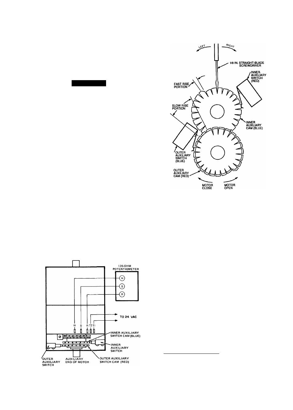
4. Adjust auxiliary cam by inserting a Vs-in. straight blade
screwdriver into slot on cam and moving TOP of screw
driver to the right or left. See Fig. 29.
5. To close auxiliary switch red and blue contacts as the
motor travels open (energizing the power exhaust mo
tor), the switch differential can only be 10 degrees on
both switches. To adjust either cam, perform the fol
lowing steps:
a. If red and blue contacts are open, rotate the cam
counterclockwise until the contacts close.
b. If the red and blue contacts are closed, rotate the cam
clockwise until the contacts open.
6. Check for proper auxiliary switching (including differ
ential) by mnning motor through full stroke, using 135
ohm potentiometer. Repeat adjustment if necessary.
7. Disconnect 135 ohm potentiometer, reconnect control
ler and place top cover on motor.
AUXILIARY END VIEW
Fig. 28 — Auxiliary Switch Stroke Adjustment
Fig. 29 — Auxiliary Switch Adjustment
NOTE: Adjusting the auxiliary switch does not require run
ning the motor.
REFRIGERANT CHARGE — All units are shipped with a
complete operating charge of R-22. See unit nameplate and
Tables la and lb for amount of charge. When charging
refrigerant system, refer to Carrier Standard Service Tech
niques, Refrigerants section. When adding a complete charge,
evacuate system using standard evacuating procedures and
weigh in the specified amount of charge. See Fig. 30 for
refrigerant circuit charging chart.
Refrigerant Feed Components
— Each refrigerant
circuit (2 per unit) has all the necessary refrigerant
controls.
Acutrol™ Refrigerant Metering Device
- Each
circuit has 12 non-adjustable metering devices. They con
trol the flow of liquid refrigerant to the evaporator coils.
Filter Drier
— Replace whenever refrigerant system is
exposed to atmosphere.
Protective Devices
COMPRESSOR PROTECTION
Overcurrent (208/230 v onlvl — Each compressor has one
manual reset, calibrated trip, magnetic circuit breaker. Do
not bypass connections or increase the size of the circuit
breaker to correct trouble. Determine the cause and correct
it before resetting the breaker.
29