Fig. 15 - field control thermostat wiring, Fig. 17 — 115-v field wiring – Carrier 50LJ User Manual
Page 20
Attention! The text in this document has been recognized automatically. To view the original document, you can use the "Original mode".
LOW-VOLTAGE
TERMINAL BLOCK
IN UNIT CONTROL BOX (PI)
THERMOSTAT/
SUBBASE
r-
0
&—J r~
@---------------' f
[wi]---------------1
^------------------------1
[
y
3----------------------
&-------------------------------
0------------------------
&--------------------
--------------------g
--------------------g
----------------^
I------------------ 0
I------------------- 0]
-----
0
I—0]
J
-----------0
____ I
Fig. 15 - Field Control Thermostat Wiring
CONVENIENCE
OUTLET
TB2
□
a
-0
1--------
1
-0
0
0
0
LEGEND
TB
— Terminal Block
NOTES:
1 Convenience outlet is field supplied and installed. Ground fault
outlet should be used.
2._______is field wiring.
Fig. 17 — 115-V Field Wiring
1 1 5 V
2 4 V
SWITCH 1 11?
I
SWITCH
5
I----- —o-'—'o—
ECON MTR
SWITCH 6
SEE NOTE 6
LEGEND
NOTES:
c
— Contactor
MTR
— Motor
ECON
— Economizer
PEC
— Power Exhaust Contactor
IFC
— Indoor (Evaporator)
PL
- Plug
Fan Contactor
TB
— Terminal Block
Switch
Switch
Switch
Switch
Switch
Switch
1
-
2
-
3 -
4 -
5
6
-
Firestat or smoke detector — normally closed.
Building pressurization switch (energize evaporator-fan
motor) — normally open.
Switch to isolate evaporator-fan motor from power exhaust
motor — normally closed
Switch purge switch (energizer power exhaust motor) —
normally open.
Switch to provide 24 v to economizer motor — normally open.
Switch to drive economizer outdoor-air damper full open —
normally closed.
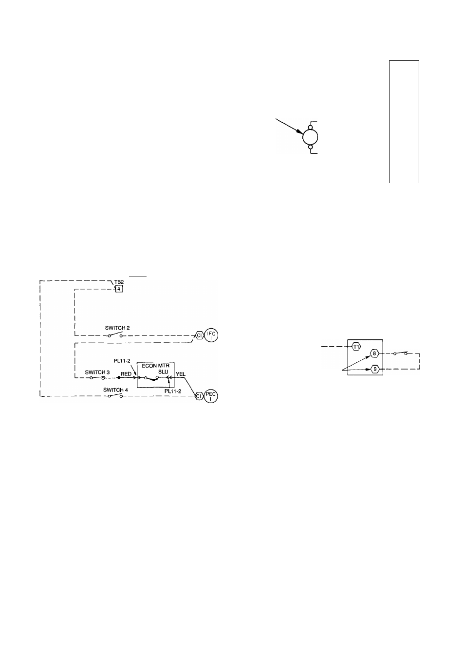
BUILDING PRESSURIZATION
SMOKE PURGE
Switch 1
Switch 1
Switch 2
Switch 3
Switch 3 (if unit equipped with power exhaust)
Switch 4
Switch 5
Switch 5
Switch 6
Switch 6
Power exhaust option available
only
on vertical supply/return
units.
In order to Install Switch 1, field must remove factory jumper
between terminals 2 and 3 on terminal block 2
______field wiring.
______ factory wiring.
All switches are field supplied.
6. Terminals 8 and 9 can be located by removing the top of the
economizer motor. Turn over top of motor to access the elec
tronic board and spade terminals.
Fig. 16 — Field Wiring for Building Pressurization
and Smoke Purge
20