Fig. 3 — unit leveling tolerances, Outdoor-air inlet adjustments, Condensate drain – Carrier 50LJ User Manual
Page 8
Attention! The text in this document has been recognized automatically. To view the original document, you can use the "Original mode".
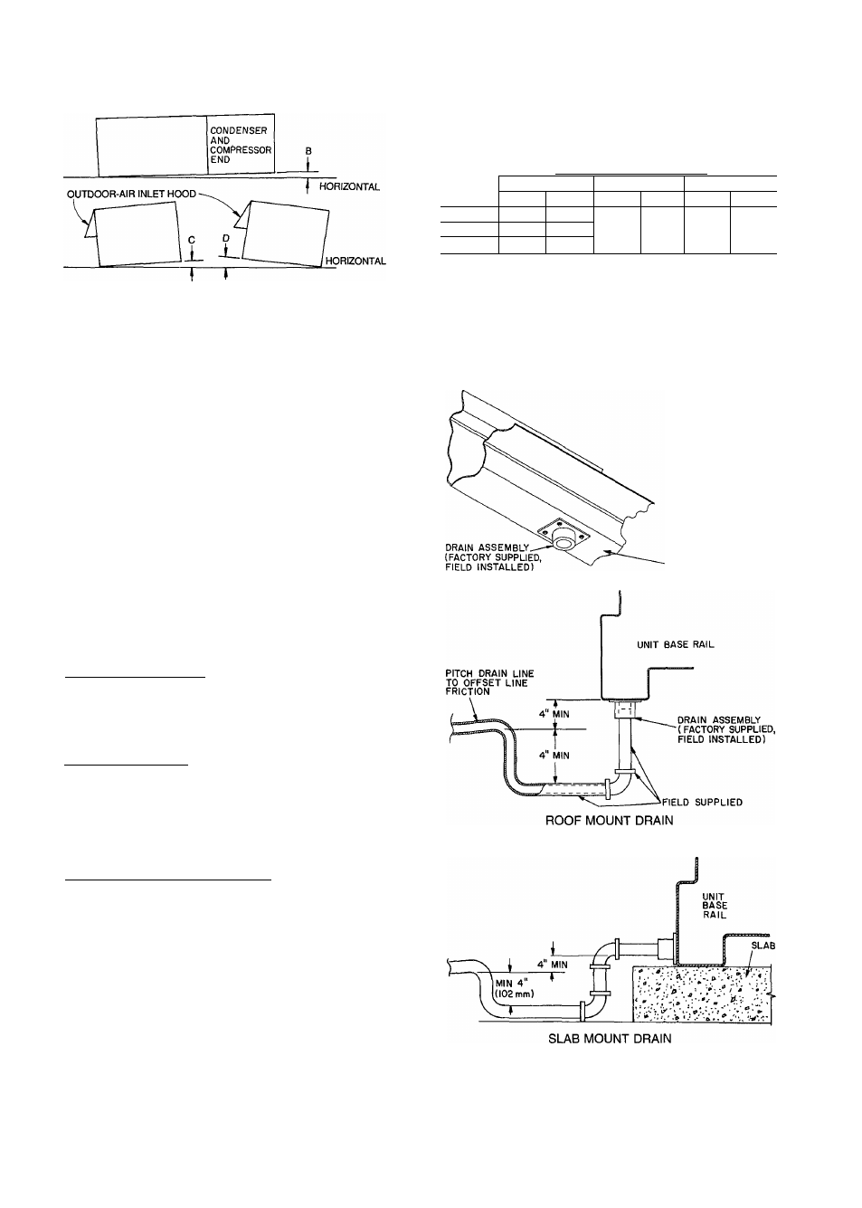
NOTE: To prevent the hazard of stagnant water build-up in the drain
pan of the evaporator section, unit can only be pitched as shown.
See Table 1 for allowable B tolerances.
DIMENSIONS (degrees and In.)
UNIT
B
C
D
Deg
In.*
Deg
In.*
Deg
In.*
48U
1 38
4.00
50LJ
1.00
3.25
.50
.75
.50
.75
50LW
1.38
4.00
'From edge of unit to horizontal
Fig. 3 — Unit Leveling Tolerances
Condensate Drain
— See Fig. 5a - 5c for drain
location. A drain assembly consisting of a 10-gage plate
with PA in. half coupling welded to it is shipped inside the
base unit, taped to the basepan in the filter section. Open
the access panel marked FILTER SECTION and fine drain
assembly and the 4 screws required to mount it in the left-
hand comer. After unit has been set in place on the roof,
remove drain assembly and attach it to the bottom of the
unit base rail using the screws provided. See Fig. 4. Use a
trap at least 4-in. deep and protect against freeze-up.
On slab mount applications, and when mounted on
sleepers, seal hole in bottom of base rail and attach drain
assembly as low as possible to side of base rail.
NOTE: Drain hole must be drilled in rail. There is no factory-
supplied drain hole in the side of the base rail.
Outdoor-Air Inlet Adjustments
ECONOMIZER SETTINGS
Enthalpy Sensor (Fig. 61 — This sensor is located on the
partition separating the outdoor air from the return air. See
Fig. 7. The enthalpy setting adjustment is on the top of the
economizer motor. See Fig. 8. For maximum benefit of out
door air, set enthalpy control to the A setting. See Fig. 8
and 9.
Mixed-Air Thermistor — The mixed-air thermistor (MAT)
set point adjustment is on the top of the economizer motor.
This motor is located in the retum-air section, and is
accessed by opening the access panel marked FILTER
SECTION. See Fig. 8. Set MAT set point adjustment dial
to the desired setting. The factory setting is 55 F ± 5° F;
the range is 40 to 90 F. The MAT is located on the filter
rack.
Minimum Damper Position Set Point — The minimum po
sition adjustment is located on the cover of the economizer
motor. See Fig. 8. Adjust by setting the fan switch to ON
position (continuous fan operation), and setting the system
selector switch to OFF position. Then turn adjustment screw
slowly until the dampers assume the desired vent position.
Do not manually operate the damper motor, damage to the
motor my result.
BOTTOM OF
BASE RAIL
Fig. 4 — Condensate Drain Piping Details