Install outdoor-air hoods – Carrier 50LJ User Manual
Page 12
Attention! The text in this document has been recognized automatically. To view the original document, you can use the "Original mode".
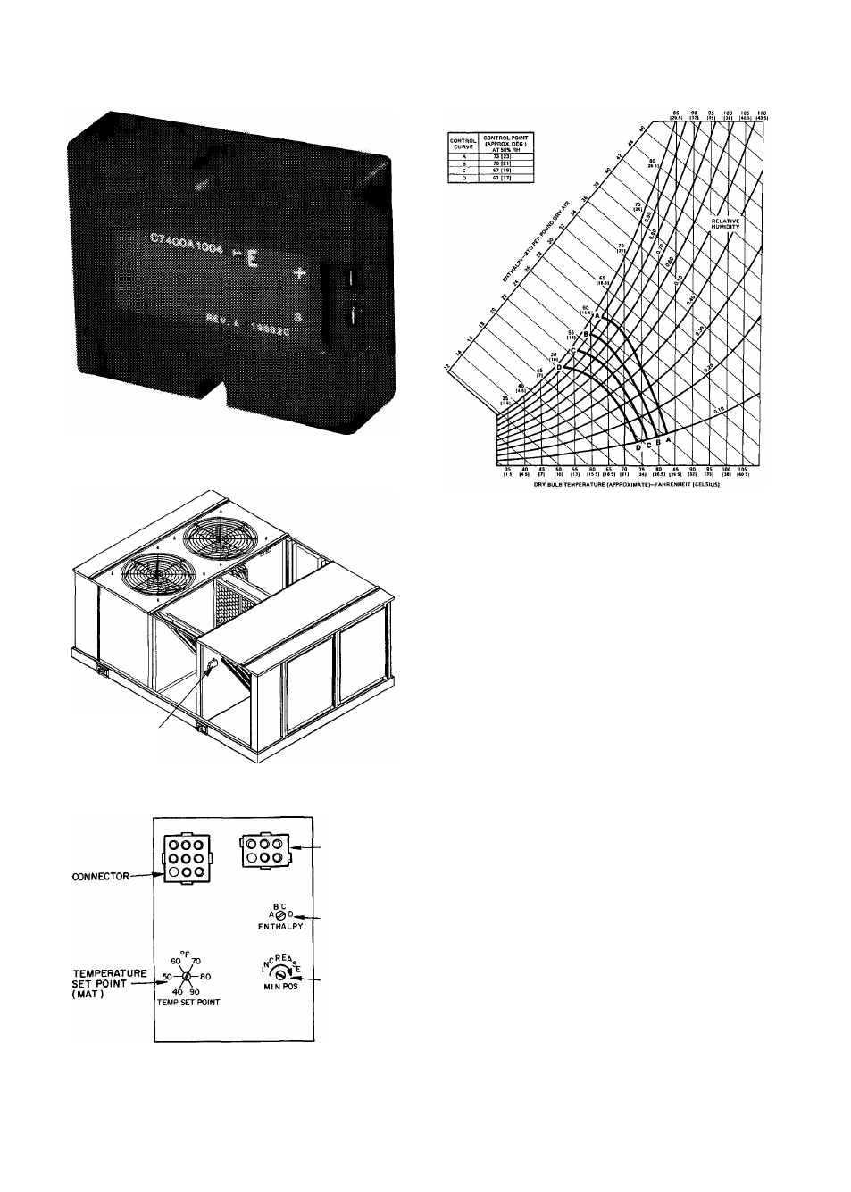
Fig. 6 — Enthalpy Sensor
ENTHALPY SENSOR
Fig. 7 — Enthalpy Sensor Location
■CONNECTOR
-ENTHALPY
-MINIMUM
POSITION
(CLOCKWISE
TO INCREASE)
Fig. 9 — Setting "A" Operating Conditions
Install Outdoor-Air Hoods
ECONOMIZER HOODS — These hoods are shipped sep
arately from the base unit in a carton. This carton contains;
3 preassembled economizer hoods
1 filter angle
3 filter retainers
6 aluminum mesh cleanable filters, 16 in. x 20 in. x 2 in.
2 channel panels "I
pj
cross-section
1 channel clip J
®
1 fastener package (taped to a hood)
The fastener package contains;
8 capscrew bolts, V4—20 x '/
2
-in. long
8 nuts, '/4—20
18 screws, V
4
AB x ys-in. long
8.3 ft of '/8-in. thick
X
'/
2
-in. wide seal strip with pressure-
sensitive adhesive on one side.
1. Remove the lag screws holding the economizer hoods
and channel panels to the shipping skid. (There are 4
lag screws per side.)
2. Remove the lag screws holding the filter angle and chan
nel clip to the shipping skid. (There are 2 lag screws
per part.)
3. The filters are wrapped to prevent shipping damage.
Remove the screws holding the filter retainers to the
hoods. (There are 4 screws per retainer.)
4. Remove wrap from filters. Do not reinstall until after
the hoods are mounted to the unit.
Fig. 8 - Enthalpy Sensor Setting, Mixed Air
Thermistor (MAT) and Economizer Minimum
Position Adjustments (Top of Economizer Motor)
12