Carrier 50LJ User Manual
Page 28
Attention! The text in this document has been recognized automatically. To view the original document, you can use the "Original mode".
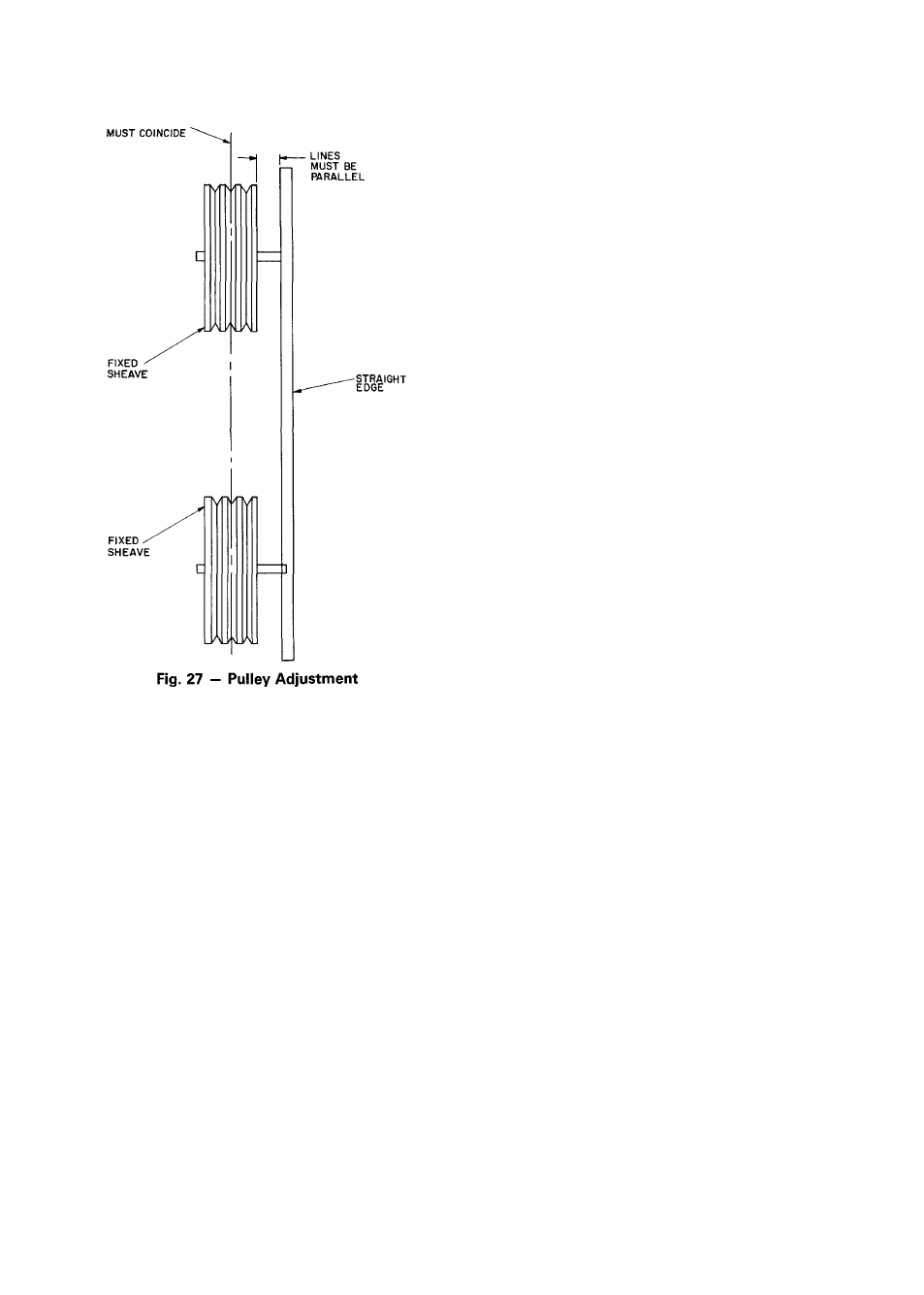
CENTER LINES
PILOT LIGHT OFF — If pilots do not light as described in
Heating section on page 23, be sure that pilot orifice is
unobstructed, then check for spark ignitor malfunctions.
If pilot flame is not sensed within 90 seconds, pilot and
main gas valves will close and will remain off for a 330-
second purge before ignition retry. The ignitor will retry
ignition indefinitely while a call for heating exists.
1. Shut off control supply power to Ignitor Control Pack
(ICP).
2. Check that spark gap is Vs-in. ± V
32
inch.
3. Check that ICP is securely grounded.
4. Check that the high-voltage lead is securely connected
between ICP and electrode body.
5. Restore power to ICP. Check that 24 v is supplied to
terminal TH of the ICP.
6
. Check unit label diagram for correct terminal usage if
any wires are removed.
AUTOMATIC PILOT ADJUSTMENT
1. Set system selector switch at OFF position to shut off
unit. Turn off power to unit.
2. Remove screw cap cover on pilot gas valve to expose
adjusting screw.
3. To ensure that main burners do not ignite, remote wire
from gas valve terminal 2. Tape wire. Do not allow wire
to be grounded.
4. Turn on power to unit. Set system selector switch to
HEAT position and set thermostat to a setting that will
call for heat. Pilot ignites.
5. With a small screwdriver, turn adjustment screw until
flame fully engulfs sensor.
6. Replace cap on pilot gas valve. Turn off power to unit.
Return valve(s) to original position.
7. Check for proper burner operation by cycling the burn
ers. Wait 30 seconds between burner cycles.
8. Check that all doors are closed securely before leaving
the unit.
GAS VALVE ADJUSTMENT - The gas valve opens and
closes in response to the thermostat or limit control. When
power is supplied to valve terminal 3 (D1 on low-heat), the
pilot valve opens to the preset position. When power is sup
plied to terminal 2 (W1 on low-heat), the main valve opens
to its preset position.
The regulator factory manifold pressure setting is stamped
on the valve body (2.7 in. wg on high-heat units and 2.9
in. wg on low-heat units).
Manifold pressure is the pressure at the factory-supplied
pressure tap on the manifold downstream of the gas valve.
This is not the same as the pressure at the tap on the gas
valve body. Always use the tap on the manifold to read
manifold pressure.
To adjust regulator:
1. Set thermostat at setting for no call for heat.
2. Turn main gas valve to OFF position.
3. Install a suitable pressure measuring device.
4. Set main gas valve to ON position.
5. Set thermostat to call for high fire (W2).
6. Remove screw cap or plastic cover covering the regula
tor adjustment screw.
7. Turn adjustment screw clockwise to increase pressure or
counterclockwise to decrease pressure.
8. Once desired pressure is established, remove pressure
measuring device and replace the screw cap.
MAIN BURNER ADJUSTMENT — Main burners are fac
tory set and should require no adjustment. However, if burner
adjustment is necessary:
1. Perform Automatic Pilot Adjustment as instructed above.
2. Turn gas valve to ON position. Allow unit to operate at
least 15 minutes with heat section access panel closed.
3. Open heat section access panel.
4. Loosen primary air shutter and adjust to a minimum open
ing of Vs inch.
5. Retighten primary air shutter and close access panel.
To check ignition of main burners and fan switch oper
ation, move thermostat dial above and below room temper
ature several times, pausing at least one minute between
cycles.
MAIN BURNER REMOVAL
1. Shut off main gas valve.
2. Shut off power to unit.
3. Unplug PL9, (and PL 10 on high heat) and all sensor and
ignitor wires.
4. Disconnect gas connection(s) from between gas valve(s)
and field-supplied piping. See Fig. 21 and 22.
5. Remove 2 screws securing burner assembly to unit.
6. Slide burner assembly from unit.
NOTE: For high-heat units (Models 48LJE) the side posts
must be removed before the burner assembly can be
removed.
28