Fig. 30 — charging chart, Gas heat, Relief devices – Carrier 50LJ User Manual
Page 30: Control circuit, 115-v, Control circuit, 24-v
Attention! The text in this document has been recognized automatically. To view the original document, you can use the "Original mode".
689
621
3^52
o
in
¡483
UJ
cc
S 41 4
in
cc
Q.
2 345
z
o
5276
:
d
in
207
1 1 1 M 1 1
OUTDOOR TEMP
F C
115 46
105 41
95 35
85 29
75 24
65 18
55 13
45 7
?"
ina.
2=
y' >
'
a:
13
in
in
1
>
" 1
X'
>
«
?
z
_J
y
orj
in
3
5
0
4
JCTION L
0
5
NE TEMPE
0
6
RATURE C
0
7
F)
0 8
0
1 1 1 1 1 1 1
-1 4 10 16 21 27
SUCTION LINE TEMPERATURE (C)
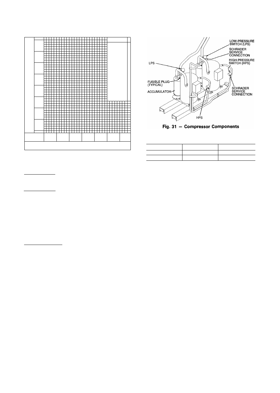
Table 6 - Pressure Switch Settings (psig)
Fig. 30 — Charging Chart
SWITCH
CUTOUT
CUT-IN
High
426 ± 7
320 ± 20
Low
7 ± 3
22 ± 5
Overtemperature — Each compressor has an internal pro
tector to protect it against excessively high discharge gas
temperatures.
r.rankcase Heater — Each compressor has a 70-watt crank
case heater to prevent absorption of liquid refrigerant by oil
in the crankcase when the compressor is idle. Since 115-v
power for the crankcase heaters is drawn from the unit con
trol circuit, main unit power must be on for the heaters to
be energized.
IMPORTANT: After a prolonged shutdown or ser
vice job, energize the crankcase heaters for 24 hours
before starting the compressors.
Compressor Lockout — If any of the safeties (high-, low-
pressure, compressor internal thermostat) trip, or if there is
loss of power to the compressors, the constant volume con
trol board will lock the compressors off. To reset, manually
move the thermostat setting.
EVAPORATOR FAN MOTOR PROTECTION - A man
ual reset, calibrated trip, magnetic circuit breaker protects
against overcurrent. Do not bypass connections or increase
the size of the breaker to correct trouble. Determine the
cause and correct it before resetting the breaker.
CONDENSER-FAN MOTOR PROTECTION - Each
condenser-fan motor is internally protected against over
temperature. Each motor is also protected against a severe
overcurrent condition by manual reset, calibrated trip, mag
netic circuit breakers. As with the circuit breakers
described previously, do not bypass connections or in
crease breaker size to correct trouble. Determine the cause
and correct it before resetting the breaker.
HIGH- AND LOW-PRESSURE SWITCHES - See Fig. 31
for compressor mounting locations. Settings for these switches
are shown in Table 6. If either switch trips, or if the
compressor overtemperature switch activates, that refriger
ant circuit will be automatically locked out by the constant
volume control board. To reset, manually move the ther
mostat setting.
Relief Devices
— All units have relief devices to pro
tect against damage from excessive pressures (i.e., fire).
These devices protect the high and low side.
Control Circuit, 115-V
- This control circuit is pro
tected against overcurrent by a 5-amp circuit breaker. Breaker
can be reset. If it trips, determine cause of trouble before
resetting.
Control Circuit, 24-V
— This control circuit is pro
tected against overcurrent by a 3.2-amp circuit breaker. Breaker
can be reset. If it trips, determine cause of trouble before
resetting.
Gas Heat
LIMITS SWITCHES — The maximum supply air temper
ature is controlled by a limit switch located in the compres
sor section. The limit is designed to trip at 100° F above the
maximum temperature shown in Table 1.
When the limit trips, the gas valve is deenergized and the
combustion air blower(s) and evaporator fan are held on
until the unit is cooled to its reset temperature. Once the
unit cools, the gas valve is reenergized.
If the thermostat stops calling for heat after the limit switch
trips, the combustion-air blower and evaporator fan are held
on until the limit cools to its reset temperature.
ROLLOUT SWITCH — This switch senses any flame or
excessive heat in the main burners and deenergizes the gas
valve. If this occurs, the gas heating system is locked out
until the rollout switch is reset manually. Reset by pressing
the button on the rollout switch. See Fig. 21 and 22.
When the rollout switch trips, it likely indicates a flue
blockage. Inspect the unit for any obstruction in the flue
system, for holes on the flue box, or for a defective
centrifugal switch or a loose combustion blower. See
Fig. 32 for proper location of the rollout capillary.
AIRFLOW SWITCH, 48LJE (HIGH HEAT) UNITS ONLY
— Shuts off the gas heat in the event there is a loss of air
over the gas cells. The airflow switch is located in the fan
section (see Fig. 5a — 5c). The switch will automatically
reset when airflow is sufficient.
30