Economizer inlet screens – Carrier 50LJ User Manual
Page 22
Attention! The text in this document has been recognized automatically. To view the original document, you can use the "Original mode".
Approved oils:
Witco Co............................................................. Suniso 3GS
Texaco, Inc....................................................Capella WF-32
Do not use drained oil and do not use any oil that has
been exposed to the atmosphere.
Unit Voltage
— Be sure power source agrees with the
unit nameplate rating.
Leak Test and Dehydration
— Be sure there are no
refrigerant leaks. All units are shipped with a complete
operating charge of R-22 (Table 1) and should be under
sufficient pressure for leak testing after installation. If there
is no system pressure, add refrigerant until a pressure is
observed and then check for leaks. After leaks are repaired,
dehydrate the system. For leak testing and dehydration
procedures, see Carrier Standard Service Techniques,
Refrigerants, Sections 6 and 7. Do not use the system com
pressors to evacuate the system.
Evaporator Fan, Belt, and Sheaves
— Belts, pul
leys, and sheaves are factory installed. All pulleys are
nonadjustable. See Table 1.
See Table 4 for complete listing of factory and field-
suipplied pulley and belt combinations. See Table 5 for air
quantity limits.
Check the lubrication of fan and motor bearings. Bear
ings are shipped full of grease for corrosion protection and
may run warm temporarily on start-up until the excess grease
has discharged. Check bearing setscrews for tightness. Also
check the tightness of the setscrews on the fan wheel and
on the fan and motor sheaves. Check fan shaft bearing mount
ings for tightness.
Recheck sheave alignment and belt tension. See Adjust
ments section on page 26 for instructions.
Hand-turn the fan to make sure the fan wheel does not
rub on the fan housing. The fan shaft and motor shaft must
be freewheeling before power is applied to the unit.
Following the necessary electrical checks, check for fan
vibration. If excessive vibration occurs, check:
• drive misalignment
• sheaves eccentric or out of balance
• wheel out of balance (replace if necessary)
Check rotation of wheel with arrow on the fan housing.
Check fan speed with a strobe-type tachometer, or use this
formula:
Pan motor rpm x motor sheave pitch diameter (in.)
Rpm
fan sheave pitch diameter (in.)
(Obtain motor rpm from the fan motor nameplate and
read sheave pitch diameters marked on the fan and motor
sheaves.
Example:
Nameplate motor rpm.......................................................1750
Motor sheave pitch diameter (in.)..................................... 6.4
Fan sheave pitch diameter (in.) ........................................12.4
^
„
1750 X 6.4
Fan Rpm =--------- ---------- = 903 rpm
The maximum allowable rpm is 1200. Excessive fan speed
may result in condensate carryover from the evaporator coil,
fan motor overload, or wheel failure. See Table 5 for Air
Quantity Limits.
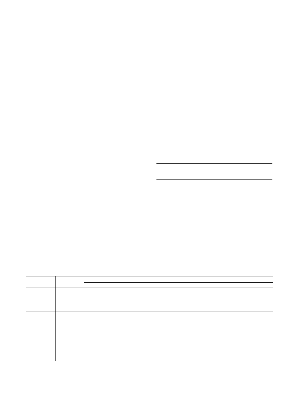
Table 5 — Air Quantity Limits
UNIT
MINIMUM
MAXIMUM
48LJD
6,000
10,000
48UE
6,162‘
10,000
50LJ,LW
6,000
10,000
‘Minimum cfm for heating operation.
Condenser Fans and Motors
— Each unit has 2
condenser fans and motors; these are factory set. See
Fig. 20 for correct location of fan in orifice. Check that
fan propeller rotation is correct; it should be counter
clockwise when facing the fans.
Return-Air Filters
— Check that the correct filters are
installed in the filter rack. See Table 1 for quantities and
sizes. Access is through the door marked FILTER SEC
TION. Do not operate the unit without retum-air filters.
Economizer Inlet Screens —
place before operating the unit.
Check that they are in
Table 4 — Evaporator-Fan Pulley Data
UNIT
FAN
MOTOR PULLEY
BLOWER PULLEY
BELT
RPM
No. Grooves — Type — In.
No. Grooves - Type — In.
No. — Type — Size
780‘
2 - 3V - 4.75
2 - 3V - 10.6
2 - 3V - 850
875
2 - 3V - 5.30
2 - 3V - 10.6
2 - 3V - 850
48U
900*
2 - 3V - 4.12
2 - 3V - 80
2 - 3V - 800
980
2 - 3V - 4.50
2 - 3V - 8.0
2 - 3V - 800
1090
3 - 3V - 5.00
3 - 3V - 80
3 - 3V - 800
1160
3 - 3V - 5 30
3 - 3V - 8.0
3 - 3V - 800
780*
2 - 3V - 4.75
2 - 3V - 10.6
2 - 3V - 560
875
2 - 3V - 5.30
2 - 3V -106
2 - 3V - 560
50LJ
900*
2 - 3V - 4.12
2 - 3V - 8.0
2 - 3V - 500
980
2 - 3V - 4.50
2 - 3V - 8.0
2 - 3V - 500
1090
3 - 3V - 5 00
3 - 3V - 80
3 - 3V - 500
1160
3 - 3V - 5 30
3 - 3V - 8.0
3 - 3V - 500
780*
2 - 3V - 4.75
2 - 3V -106
2 - 3V - 850
875
2 - 3V - 5 30
2 - 3V - 10.6
2 - 3V - 850
50LW
900*
2 - 3V - 4.12
2 - 3V - 80
2 - 3V - 800
980
2 - 3V - 4 50
2 - 3V - 8.0
2 - 3V - 800
1090
3 - 3V - 5.00
3 - 3V - 8.0
3 - 3V - 800
1160
3 - 3V - 5.30
3 - 3V - 8.0
3 - 3V - 800
‘Indicates standard or optional pulley combinations available as shown in Tales la and 1b. All other
combinations are field supplied.
NOTE: The minimum speed with high eiectric heat option is 780 rpm
22