Carrier 50LJ User Manual
Page 10
Attention! The text in this document has been recognized automatically. To view the original document, you can use the "Original mode".
UNIT SIZE
WEIGHr
A
B
C
D
E
F
Lb
Kg
mm
Ft-ln.
mm
Ft-in
mm
Ft-in.
mm
Ft-in.
mm Ft-in
mm
Ft-in.
50LJ024
2565
1163.5
1556
5-1V4 1680
5-6V8 3141
10-3'Vi 6 526
1-8"/i6
807
2-7%
2048
6-8%
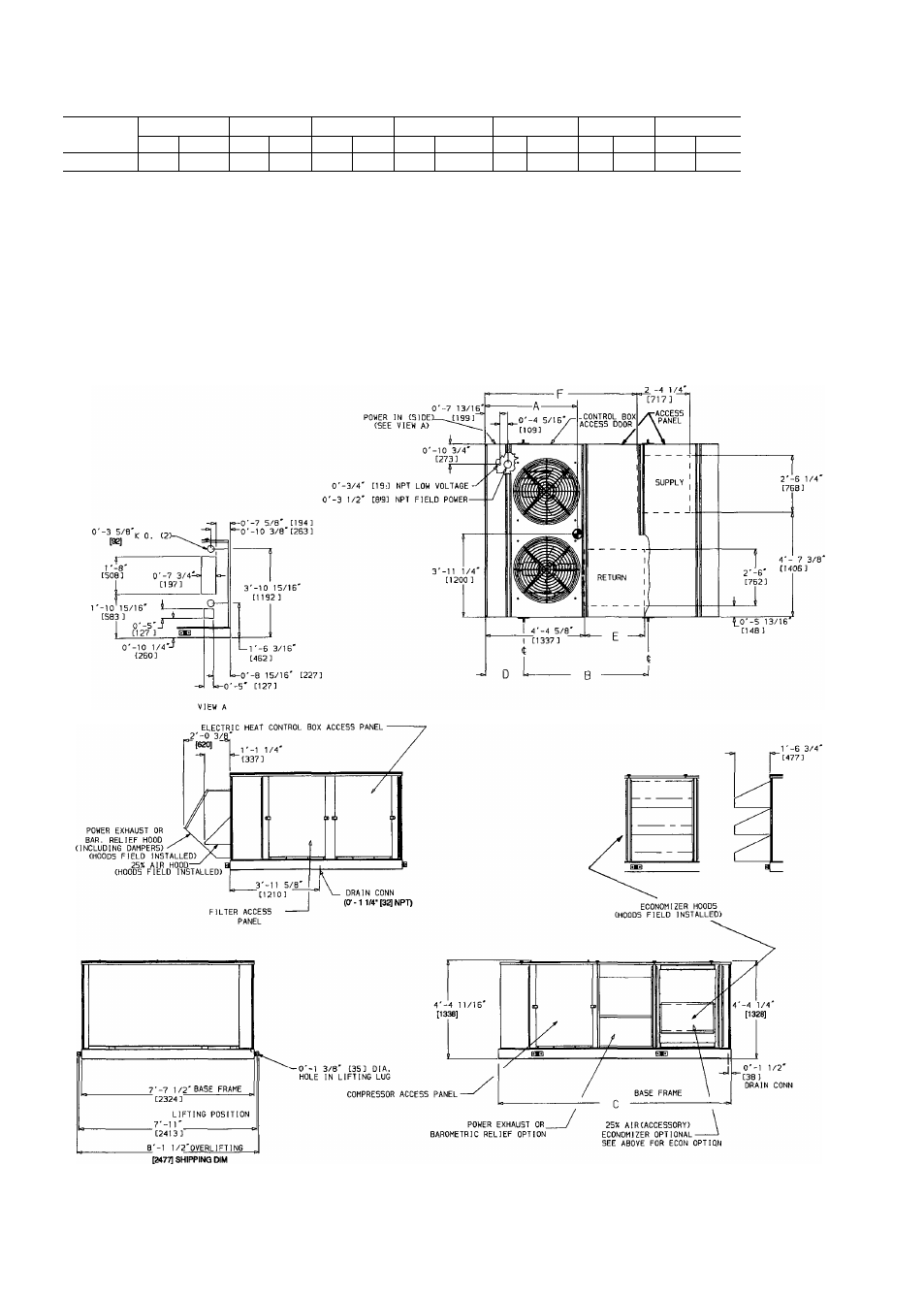
*See note 10
NOTES:
1. Dimensions in [ ] are in miiiimeters.
Center of gravity.
3. Allow 12'-0" [3658] at top and 6'-0" [1829] on sides for service and operational clearance
4. On multiunit applications aliow 12'-0" [3658] between adjacent condensers and economizers
5. For smaller service and operational clearances, contact Carrier Application Engineering Department
6. Vertical discharge ducts are designed to be attached to accessory roof curb If unit is mounted on dunnage,
it is recommended the ducts be supported by cross braces as done on the accessory roof curb
7 Always line up condenser end of unit tight against the roof curb.
8 Units with power exhaust require a 90 degree elbow in return-air duct.
9. Units with electric heat require a 90 degree elbow in supply-air duct.
10 Weight of unit includes optional economizer For unit without economizer, deduct 130 lb (59 Kg)
Fig. 5b — Base Unit Dimensions, 50LJ024 Units
10