Start-up, Installation locations for flue hood assemblies, Fig. 19 — flue hood details – Carrier 50LJ User Manual
Page 21
Attention! The text in this document has been recognized automatically. To view the original document, you can use the "Original mode".
i(f
Gas Piping
— Unit is equipped for use with natural gas
only. Installation must conform to local building codes, or
in the absence of local codes, with the NFGC (National
Fuel Gas Code), ANSI (American National Standards
Institute) Z223.1-1984.
A '/sin. NPT tapping plug, accessible for test gage con
nection, must be field installed immediately upstream of
gas supply connection to unit. See Fig. 18.
Natural gas pressure at unit gas connection must not be
less than 5 in. wg or greater than 14 in. wg.
Size gas supply piping for 0.5 in. wg maximum pressure
drop. Do not use supply pipe smaller than unit gas
connection.
A
CAUTION
Disconnect gas piping from unit when leak testing at
pressures greater than 0.5 psig. Pressures greater than
0.5 psig will cause gas valve damage resulting in a haz
ardous condition. If gas valve is subjected to pressure
greater than 0.5 psig, it must be replaced.
UNION (FOR SERVICING)
*NPT plug is field supplied.
NOTE: Follow all local codes.
Fig. 18 - Gas Piping Detaiis
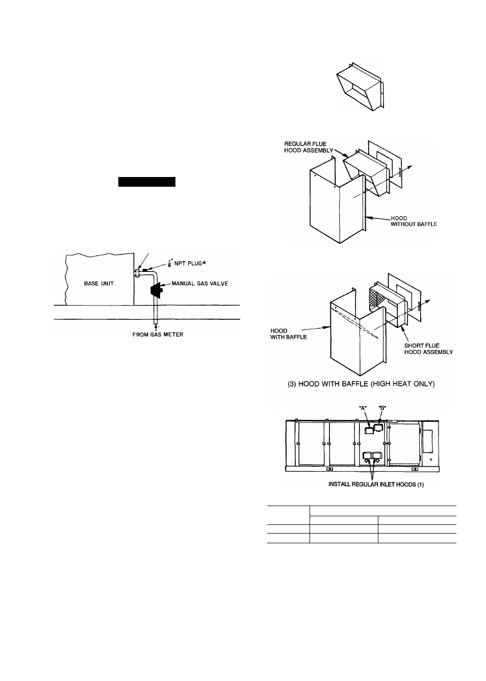
Installing Flue/lnlet Hoods
— The flue/inlet hoods
are shipped in a bag taped to the basepan under the unit
fan. Remove the shipping block-offs and install hoods as
shown in Fig. 5a and 19. Use RTV sealant to provide rain
proof seal between hoods and door.
START-UP
Unit Preparation
— Check to see that unit has been
installed in accordance with these Installation Instructions
and all applicable codes.
Interhal Wiring
— Check all electrical connections in
the unit control box; tighten as required.
Refrigerant Service Ports
— Each unit system has
3 Schrader-type service ports, one on the suction line, one
on the liquid line, and one on the compressor discharge line.
Be sure that caps on the ports are tight.
Crankcase Heaters
— The crankcase heaters must be
firmly locked onto the compressors. The crankcase heaters
are energized when there is power to the unit. Crankcase
heaters must be energized for at least 24 hours prior to unit
start-up in order to remove liquid refrigerant from the com
pressor crankcase.
Compressor Oil
— All units are factory charged with
oil. The initial charge is 128 oz. The recharge is 124 oz.
See Carrier Standard Service Techniques, Refrigerants, for
procedures to add or remove oil.
(1) REGULAR INLET HOOD
(2) HOOD WITHOUT BAFFLE (LOW HEAT ONLY)
Installation Locations for Flue Hood Assemblies
UNIT
LOCATION
TYPE
“A”
“B”
High Heat
Hood With Baffle (3)
Hood With Baffle (3)
Low Heat
-
Hood Without Baffle (2)
NOTE: Numbers in ( ) refer to type of hood to install in location
indicated.
Fig. 19 — Flue Hood Details
If it is necessary to remove oil, do not remove any oil
until the compressor crankcase heater has been ON for at
least 24 hours. When additional oil or a complete charge is
needed, use only Carrier-approved compressor oil.
21