Carrier 50LJ User Manual
Page 33
Attention! The text in this document has been recognized automatically. To view the original document, you can use the "Original mode".
8
. To verify compressor lockout logic:
a. Disconnect CLO sensor wires connected to CLOl at
the control board. Check wires for continuity. If there
is no continuity, replace the sensor.
b. Connect the multimeter to read voltage between Pin
X at plug PI and ground.
c. Turn unit power on and check the multimeter. Within
a few seconds the meter should indicate 24 v. If it
does not, the control board is defective and must be
replaced.
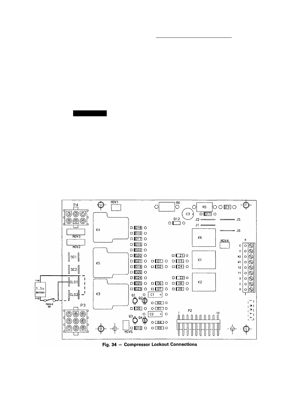
d. Turn unit power off. Use a toggle switch to connect
a fresh 1.5-v battery to the terminals marked CLOl
as shown in Fig. 34.
A
CAUTION
The negative (- Ve) pole of the battery must be
connected to the inner terminal and the positive
(+ Ve) pole must be connected to the outer ter
minal as shown in Fig. 34.
e. Turn unit power on and use the toggle switch to make
and break the connection between the outer CLOl
terminal and the positive (-h Ve) pole of the battery.
If the multimeter shows 24 v when battery is dis
connected and no voltage when the battery is con
nected, the CLO logic is good. If the multimeter shows
no change, the CLO logic is defective and the board
must be replaced.
1. Be sure unit power is OFF. Disconnect the 2 wires at
tached to the terminals marked SC2.
2. Check continuity between the 2 wires. If there is no con
tinuity, the problem is external to the control board
(possibly the pressure switches). If there is continuity,
proceed to Step 3.
3. Reconnect the wires removed in Step 1 above.
4. Turn unit power off. Disconnect plug PI from the con
trol board and install jumper wire across Pins R and Y2
at plug PI. (This may have already been done in the
Compressor no. 1 troubleshooting section.)
5. Connect a voltmeter across the coil for Compressor no.
2
contactor.
6
. Energize unit and monitor the voltage for a few
seconds.
Sym ptom : Com pressor No. 2 W ill Not Operate.
IMPORTANT: Do not run compressor too long.
7. a.
b.
If proper voltage is indicated at the contactor, but
contactor fails to close, replace contactor.
If voltage is indicated for a few seconds (i.e., the
contactor momentarily pulls in and is then de
energized), the Compressor Lockout (CLO) logic has
shut down the unit. This is an indication that the board
is not sensing proper compressor current, or that one
of the safeties has tripped. Proceed to Step 8 to ver
ify compressor lockout logic operation.
If proper voltage is indicated at the contactor and con
tactor closes, the board is operating properly.
PI
33