Field electrical connections – Carrier 50LJ User Manual
Page 15
Attention! The text in this document has been recognized automatically. To view the original document, you can use the "Original mode".
terminals on terminal blocks. See control wiring section on
page 17.
ROUTING THROUGH SIDE OF UNIT - When 200-amp
or smaller disconnect is used, route power wiring in
field-supplied watertight conduit into unit through 3Vs in.
knockout. Strain relief (field supplied) must be used in knock
out. When 400-amp disconnect is used, remove 7% in. x
20-in. block-off in comer post and use field-supplied elbow
to route conduit through comer post to the control box.
Use field-supplied strain relief going into control box through
4
V
2
in. diam hole provided. After wires are in unit control
box, connect to power terminal block. See power wiring
section below.
Bring low-voltage control wiring through field-drilled Vs-in.
diameter hole in condenser side post. Use strain relief go
ing into one-in. diameter hole in upper righthand comer of
unit control box.
After wiring is in control box, make connection to proper
terminals on terminal blocks. See control wiring section on
page 17.
Field Electrical Connections
POWER WIRING (All units) — Units are factory wired
for the voltage shown on the unit nameplate. The main ter
minal block is suitable for use with aluminum or copper
wires.
When installing units, provide a disconnect per NEC
(National Electrical Code) of adequate size (MOCP [max
imum overcurrent protection] of unit is on the informative
plate). All field wiring must comply with NEC and all local
codes. Size wire based on MCA (minimum circuit amps)
on the unit informative plate. See Fig. 13 for power wiring
connections to the unit power, terminal block and equip
ment ground.
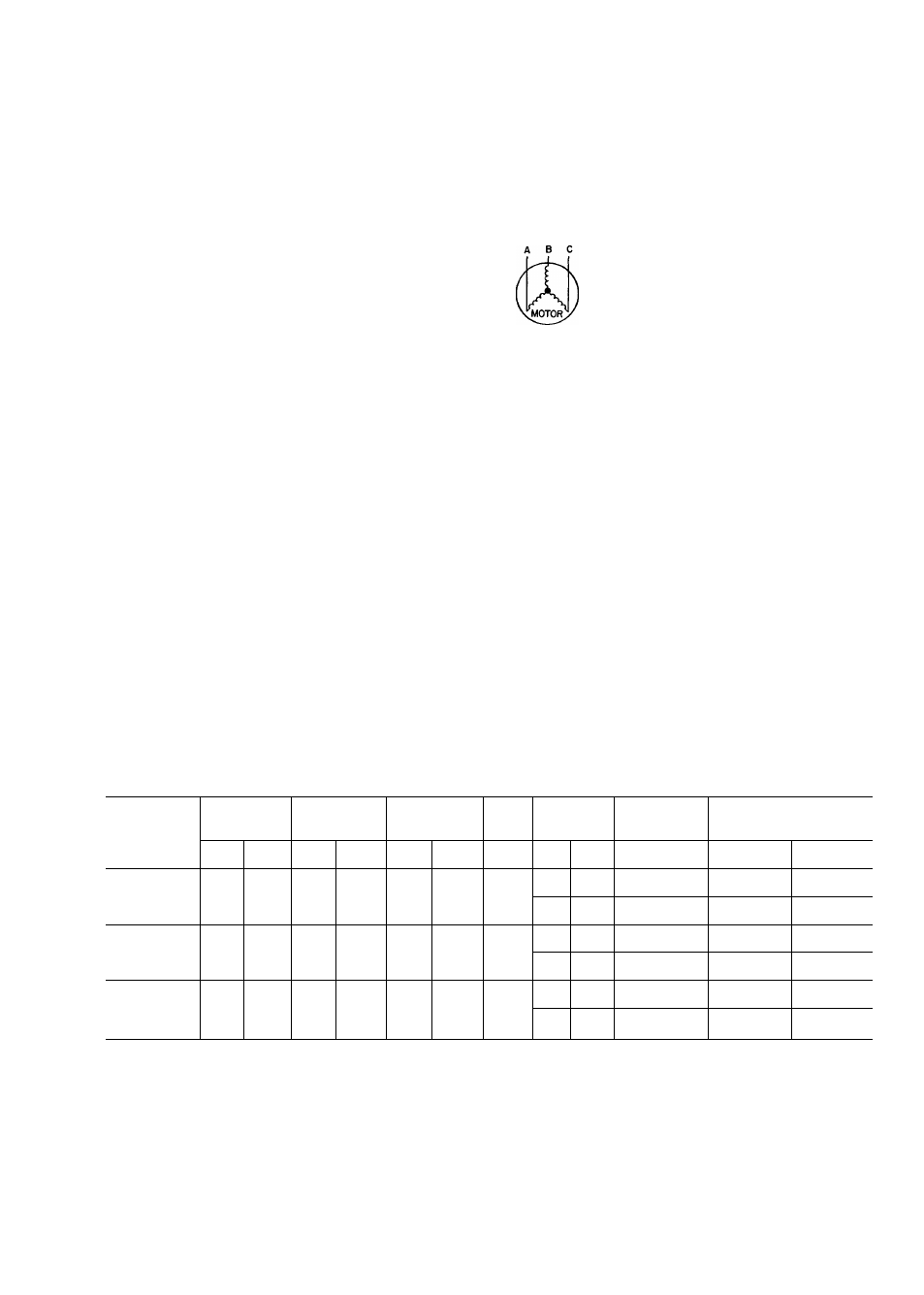
Operating voltage to the compressor must be within the
voltage range indicated on the unit nameplate. Voltages be
tween phases must be balanced within 2%, and the current
must be balanced within 10%. See Tables 2 and 3 for unit
electrical data.
= 100
X
Use the following formula to determine the percent volt
age imbalance.
% Voltage Imbalance
max voltage deviation from average voltage
average voltage
Example: Supply voltage is 460-3-60
AB =452
V
BC =464
V
AC =455
V
452 +462 -1-455
Average Voltage
1371
3
= 457
Determine maximum deviation from average voltage:
(AB) 457 - 452 =5 v
(BC) 464 - 457 =7
V
(AC) 457 - 455 =2 v
Maximum deviation is 7 v.
Determine pereent voltage imbalance:
7
% Voltage Imbalance = 100 x
457
= 1.53%
This amount of phase imbalance is satisfactory as it is be
low the maximum allowable 2%.
IMPORTANT: If the supply voltage phase im
balance is more than 2%, contact local utility
immediately.
Unit failure as a result of operation on improper line
voltage or excessive phase imbalance constitutes abuse and
may cause damage to electrical components. Such opera
tion would invalidate any applicable Carrier warranty.
Table 2 — Electrical Data, 48LJ024
NOMINAL
V-PH-HZ
VOLTAGE
RANGE
COMPR
NO. 1
COMPR
NO. 2
OFM
IFM
POWER
EXHAUST
FAN MOTOR
POWER SUPPLY
Min
Max
RLA
LRA
RLA
LRA
Total
FLA
Hp
FLA
FLA
MCA
MOCP
Fuse Only
208/230-3-60
187
254
38.5
193.0
38 5
193.0
10.8
50
15.2
6.6/6.0
101 8/112.6
108.4/118 6
150/150
150/150
7.5
22.0
6.6/6.0
108.6/119.4
115.2/125.4
150/150
150/150
460-3-60
414
508
193
96.5
193
96.5
5.4
50
7.2
30.0
56.0
59 0
70
70
7.5
10.5
3.0
59.3
62.3
70
80
575-3-60
518
632
144
77.2
144
77.2
48
50
5.2
2.4
42.4
44 8
50
50
7.5
86
2.4
45.8
48.2
60
60
FLA —
Full Load Amps
Hp —
Nominal Horsepower
IFM —
Indoor (Evaporator) Fan Motor
LRA —
Locked Rotor Amps
LEGEND
MCA
—
Minimum Circuit Amps (for wire sizing)
MOCP —
Maximum Overcurrent Protection
OFM
—
Outdoor (Condenser) Fan Motor
RLA
—
Rated Load Amps
15