Carrier 50PEC09-18 User Manual
Page 31
31
AHRI/ISO/ASHRAE Standard 13256-1 rating test, for initial
start-up in winter.
Unit Start-Up
1. Turn the thermostat fan position to “ON”. Blower should
start.
2. Balance air flow at registers.
3. Adjust all valves to their full open positions. Turn on the
line power to all heat pumps.
4. Room temperature should be within the minimum and
maximum ranges of Table 4. During start-up checks, loop
water temperature entering the heat pump should be be-
tween 16 C and 35 C.
5. Two factors determine the operating limits of Carrier heat
pumps, return air temperature and water temperature.
When any one of these factors is at a minimum or maxi-
mum level, the other factor must be at normal level to en-
sure proper unit operation.
a. Adjust the unit thermostat to the warmest setting.
Place the thermostat mode switch in the “COOL”
position. Slowly reduce thermostat setting until the
compressor activates.
b. Check for cool air delivery at the unit grille within
a few minutes after the unit has begun to operate.
Units have a five minute time delay in the control
circuit that can be eliminated on the control board
if needed.
c. Check the elevation and cleanliness of the conden-
sate lines. Dripping may be a sign of a blocked
line. Check that the condensate trap is filled to pro-
vide a water seal.
d. Check the temperature of both entering and leaving
water. See Table 8. If temperature is within range,
proceed with the test. If temperature is outside the
range, check refrigerant pressures.
e. Check air temperature drop across the air coil
when compressor is operating. Air temperature
drop should be between 8° C and 14° C.
f. Turn thermostat to “OFF” position. A hissing noise
indicates proper functioning of the reversing valve.
6. Allow five (5) minutes between tests for pressure to
equalize before beginning heating test.
a. Adjust the thermostat to the lowest setting. Place
the thermostat mode switch in the “HEAT” posi-
tion.
b. Slowly raise the thermostat to a higher temperature
until the compressor activates.
c. Check for warm air delivery within a few minutes
after the unit has begun to operate.
d. Refer to Table 8. Check the temperature of both
entering and leaving water. If temperature is within
range, proceed with the test. If temperature is out-
side the range, check refrigerant pressures.
e. Check air temperature rise across the air coil when
compressor is operating. Air temperature rise
should be between 11° C and 17° C.
f. Check for vibration, noise, and water leaks.
7. If unit fails to operate, perform troubleshooting analysis
(see troubleshooting section). If the check described fails
to reveal the problem and the unit still does not operate,
contact a trained service technician to ensure proper diag-
nosis and repair of the equipment.
When testing is complete, set system to maintain desired
comfort level.
Flow Regulation —
Flow regulation can be accom-
plished by two methods. Most water control valves have a
built-in flow adjustment valve. Determine the flow rate by
measuring the pressure drop through the unit heat exchanger.
See Table 9. Adjust the water control valve until a flow of 2.0
to 3.9 L/m per kW cooling is achieved. Since the pressure
constantly varies, two pressure gages may be needed.
An alternative method for regulating flow is to install a flow
control device. These devices are typically an orifice of plastic
material mounted on the outlet of the water control valve,
designed to allow a specified flow rate. Occasionally these
valves produce a velocity noise that can be reduced by
applying some back pressure. To accomplish this, slightly close
the leaving isolation valve of the water regulating device.
Antifreeze —
In areas where entering loop temperatures
drop below 4.4 C or where piping will be routed through areas
subject to freezing, antifreeze is needed.
Alcohols and glycols are commonly used as antifreeze
agents. Freeze protection should be maintained to 8.3° C below
the lowest expected entering loop temperature. For example, if
the lowest expected entering loop temperature is –1.1 C, the
leaving loop temperature would be –5.6 to –3.9 C. Therefore,
the freeze protection should be at –9.4 C (–1.1 C – 8.3 C =
–9.4 C).
Calculate the total volume of fluid in the piping system. See
Table 10. Use the percentage by volume in Table 11 to deter-
mine the amount of antifreeze to use. Antifreeze concentration
should be checked from a well mixed sample using a hydrome-
ter to measure specific gravity.
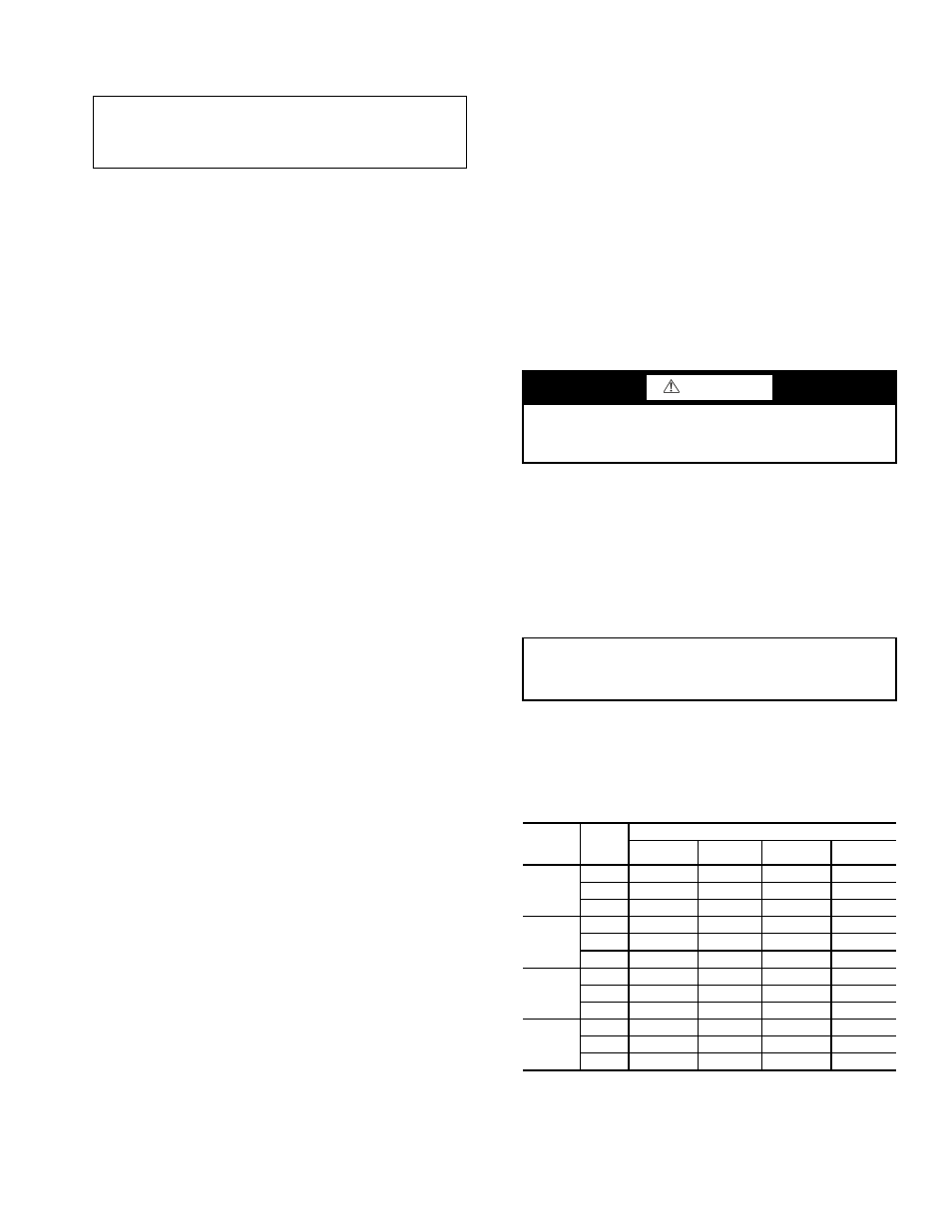
Table 9 — Coaxial Water Pressure Drop
IMPORTANT: These operating limits are not normal or
continuous operating conditions. It is assumed that such a
start-up is for the purpose of bringing the building space up
to occupancy temperature.
CAUTION
DO NOT use “Stop Leak” or any similar chemical agent in
this system. Addition of these chemicals to the loop water
will foul the system and inhibit unit operation.
IMPORTANT: All alcohols should be pre-mixed and
pumped from a reservoir outside of the building or intro-
duced under water level to prevent alcohols from fuming.
50PEC
UNIT
SIZE
L/m
PRESSURE DROP (kPa)
-1 C
10 C
21 C
32 C
09
4.2
11.0
8.3
6.9
6.2
6.1
17.9
15.2
13.8
13.1
8.7
31.0
26.2
24.1
20.7
12
5.7
14.5
12.4
10.3
9.0
8.7
31.0
26.2
24.1
20.7
11.4
46.9
40.0
33.8
31.0
15
7.2
10.3
6.9
6.2
5.5
10.6
20.7
15.8
13.8
11.7
14.0
32.4
26.9
22.7
20.0
18
8.7
15.2
12.4
10.3
9.0
12.9
30.3
26.2
23.4
20.7
17.1
47.5
41.3
35.8
33.1