Deluxe d control accessory relay configura- tions, Start-up, Operating limits – Carrier 50PEC09-18 User Manual
Page 30: Caution, Warning
30
Select OFF for set point of 10.0 C or select ON for set point of
4.4 C.
If switch 8 is set for 10.0 C, then the compressor will be
used for heating as long as the FP1 is above 10.0 C. The com-
pressor will not be used for heating when the FP1 is below
10.0 C and the compressor will operate in emergency heat
mode, staging on EH1 and EH2 to provide heat. If a thermal
switch is being used instead of the FP1 thermistor, only the
compressor will be used for heating mode when the FP1 termi-
nals are closed. If the FP1 terminals are open, the compressor is
not used and the control goes into emergency heat mode.
DIP SWITCH BLOCK 2 (S2) — The following set of DIP
switches is used to configure accessory relay options.
Switches 1 to 3 — These DIP switches provide selection of
Accessory 1 relay options. See Table 6 for DIP switch
combinations.
Table 6 — DIP Switch Block S2 —
Accessory 1 Relay Options
LEGEND
NOTE: All other DIP switch combinations are invalid.
Switches 4 to 6 — These DIP switches provide selection of
Accessory 2 relay options. See Table 7 for DIP switch
combinations.
Table 7 — DIP Switch Block S2 —
Accessory 2 Relay Options
LEGEND
NOTE: All other switch combinations are invalid.
Auto Dehumidification Mode or High Fan Mode — Switch
7 provides selection of auto dehumidification fan mode or high
fan mode. In auto dehumidification fan mode, the fan speed
relay will remain off during Cooling Stage 2 if terminal H is
active. In high fan mode, the fan enable and fan speed relays
will turn on when terminal H is active. Set the switch to ON for
auto dehumidification fan mode or to OFF for high fan mode.
Switch 8 — Not used.
Deluxe D Control Accessory Relay Configura-
tions —
The following accessory relay settings are applica-
ble for Deluxe D control only:
CYCLE WITH COMPRESSOR — In this configuration, the
relay will be ON any time the compressor relay is on.
DIGITAL NIGHT SETBACK (NSB) — In this configura-
tion, the relay will be ON if the NSB input is connected to
ground C.
NOTE: If there are no relays configured for digital NSB, then
the NSB and OVR (override) inputs are automatically config-
ured for mechanical operation.
MECHANICAL NIGHT SETBACK — When NSB input is
connected to ground C, all thermostat inputs are ignored. A
thermostat setback heating call will then be connected to the
OVR input. If OVR input becomes active, then the Deluxe D
control will enter night low limit (NLL) staged heating mode.
The NLL staged heating mode will then provide heating during
the NSB period.
WATER VALVE (SLOW OPENING) — If relay is config-
ured for water valve (slow opening), the relay will start 60 sec-
onds prior to starting compressor relay.
START-UP
Use the procedure outlined below to initiate proper unit
start-up:
1. Adjust all valves to the full open position and turn on the
line power to all heat pump units.
2. Operate each unit in the Cooling mode first.
Room temperature should be in the normal range
(i.e., approximately 10.0 to 26.7 C dry bulb). Loop water
temperature entering the heat pumps should be at least
4.4 C but not in excess of 43.3 C. Refer to Table 8 for
more specific information on the operating parameters of
units.
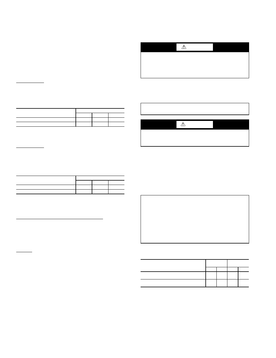
Table 8 — Water Temperature Change
Through Heat Exchanger
Operating Limits
ENVIRONMENT — This equipment is designed for indoor
installation ONLY.
POWER SUPPLY — A voltage variation of ± 10% of name-
plate utilization voltage is acceptable.
50PEC UNIT STARTING CONDITIONS — The 50PEC
units will start and operate at an ambient temperature of 10.0 C
with entering-air temperature at 10.0 C, entering water at
15.6 C, and with both air and water at the flow rates used in the
ACCESSORY 1
RELAY OPTIONS
DIP SWITCH POSITION
1
2
3
Digital NSB
Off
On
On
Water Valve — Slow Opening
On
Off
On
NSB — Night Setback
ACCESSORY 2
RELAY OPTIONS
DIP SWITCH POSITION
4
5
6
Digital NSB
Off
On
On
Water Valve — Slow Opening
On
Off
On
NSB — Night Setback
CAUTION
To avoid equipment damage, DO NOT leave system filled
in a building without heat during the winter unless anti-
freeze is added to system water. Condenser coils never
fully drain by themselves and will freeze unless winterized
with antifreeze.
IMPORTANT: This equipment is designed for indoor
installation ONLY.
WARNING
When the disconnect switch is closed, high voltage is pres-
ent in some areas of the electrical panel. Exercise caution
when working with the energized equipment.
IMPORTANT: Three factors determine the operating limits
of a unit: (1) return-air temperature, (2) water temperature
and (3) ambient temperature. Whenever any one of these
factors is at a minimum or maximum level, the other two
factors must be at normal levels to ensure proper unit oper-
ation. Flow rates must be at nominal AHRI (Air Condition-
ing, Heating, and Refrigeration Institute) / ISO
(International Organization for Standardization)/ ASHRAE
(American Society of Heating, Refrigerating and Air Con-
ditioning Engineers) 13256-1 standards.
WATER FLOW RATE (GPM)
COOLING
RISE (°C)
HEATING
DROP (°C)
Min
Max
Min
Max
For Closed Loop: Ground Source or
Cooling/Boiler Systems at 3.9 L/m per kW
5.0
6.7
2.2
4.4
For Open Loop: Ground Water Systems at
2.0 L/m per kW
11.1
14.4
5.6
9.4