Carrier 50PEC09-18 User Manual
Page 18
18
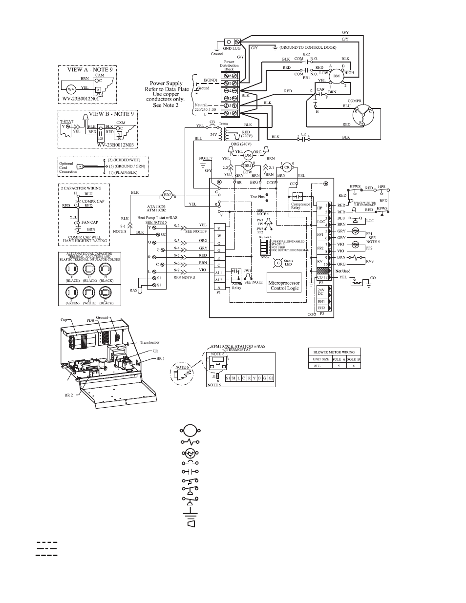
Fig. 17 — 50PEC Unit Manual or Auto Changeover with Complete C Controller Wiring
Complete C
10
Complete C
LEGEND
NOTES:
1. Compressor and blower motor thermally pro-
tected internally.
2. All wiring to the unit must comply with local
codes.
3. Transformer is wired to 240-V (ORG) lead for
240-1-50 units. For 220-1-50 operation, switch
the RED and ORG leads at L1 and insulate the
RED lead. Transformer is energy limiting or
may have a circuit breaker.
4. FP1 thermistor provides freeze protection for
water. When using anti-freeze solutions, cut
JW3 jumper.
5. For remote sensor, position jumper J1 on upper
2 pins.
6. For metric display, position jumper on 1 pin.
7. Transformer secondary ground via GRN/YEL
wire from C to control box.
8. Mate-N-Lok† plug is optional.
9. See view A for wiring of units with water valve
(part no. 23B00112N01) or view B for units with
water valve (part no. 23B00112N03).
10. Factory cut jumper (JW1). Dry contact will be
available between AL1 and AL2.
AL
—
Alarm Relay Contacts
BM
—
Blower Motor
BR
—
Blower Relay
CAP
—
Capacitor
CB
—
Circuit Breaker
CO
—
Sensor, Condensate Overflow
CR
—
Compressor Relay
DM
—
Damper Motor
ES
—
End Switch
FP1
—
Sensor, Water Coil Freeze Protection
FP2
—
Sensor, Air Coil Freeze Protection
HPS
—
High Pressure Switch
HPWS
—
High Presure Water Switch
JW1
—
Jumper Wire for Alarm
LOC
—
Loss of Charge Pressure Switch
PDB
—
Power Distribution Block
RAS
—
Return Air Sensor
RVS
—
Reversing Valve Solenoid
TRANS
—
Transformer
WV
—
Water Valve
----------
Field Line Voltage Wiring
Field Low-Voltage Wiring
Printed Circuit Trace
Option Low Voltage Wiring
*Optional wiring.
†Registered trademark of AMP Incorporated.
Relay/Contactor Coil
Solenoid Coil
Thermistor
Circuit Breaker
Relay Contacts-N.O.
Switch-Temperature
Switch-High Pressure
Switch-Low Pressure
Ground
Wire Nut
Mate-N-Lok
>>