Carrier 50PEC09-18 User Manual
Page 14
14
NO
TES:
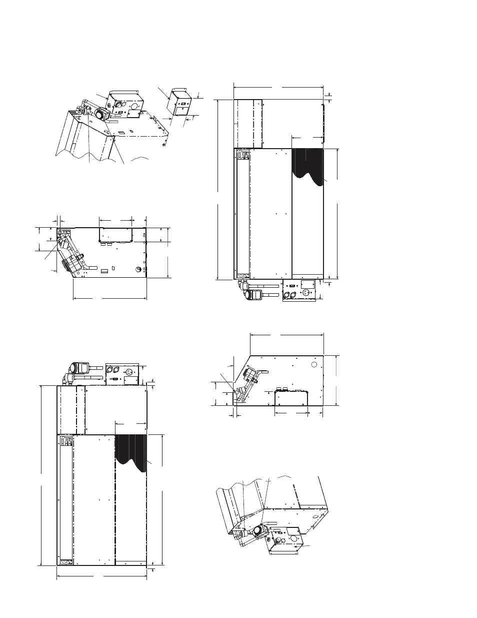
1.
Dimensions sho
w
n are in inches
. Dimens
ions in parent
heses are in millimeters
.
2.
Optio
nal au
toflo
w
v
alv
e
, motor
iz
ed w
a
ter v
a
lv
e
and disconnect bo
x are sho
w
n
.
3.
Chassis can mount directly on
floor
.
F
ig
. 12
— 50PEC09
-15
Cha
s
s
is
Dimens
io
ns — Fr
ont
Re
turn
Power
S
upply
Blower Deck
Compre
ss
or
Acce
ss
P
a
nel
Control Box
40.98
(1041)
4.46
(1
13)
0.75
(19)
0.75
(19)
20.50
(521)
1
1.54
(293)
16.66
(423)
30°
0.87
(22)
Hard Wire
Power
S
upply
Blower Deck
Filter
Compre
ss
or
Acce
ss
P
a
nel
Control Box
7.50
(191)
0.87
(22)
1
1.54
(293)
3.42
(87)
16.66
(423)
30
°
3.01
(76)
5.36
(136)
0.75
(19)
0.75
(19)
4.46
(1
13)
20.50
(521)
40.98
(1040)
3.01
(76)
5.36
(136)
Optional
Motorized
W
ater V
alve
Optional
Autoflow
V
alve
Optional
Fu
s
ed Di
s
connect Box
(mo
u
nted to c
ab
inet
not ch
ass
is
)
Optional
Motorized
W
ater V
alve
Optional
Autoflow
V
alve
3.56
(90)
7.50
(191)
3.42
(87)
3.56
(90)
Optional Fu
s
ed
Di
s
connect Box
(mo
u
nted to c
ab
inet
not ch
ass
is
)
Power
su
pply enter
s
Bottom of Box
Optional Di
s
connect
Only Box
(All Config
u
ra
tion
s
)
Power
su
pply enter
s
Bottom of Box
4.46
(113)
4.56
(116)
Power
su
pply enter
s
Bottom of Box
Filter
7.38
(187)
30.00
(762)
7.38
(187)
Blower
S
creen
Blower
S
creen
30.00
(762)
Righ
t Hand
Co
nfi
guratio
n
a50-8348
L
eft Ha
nd
C
o
n
fig
ur
atio
n