Carrier 50PEC09-18 User Manual
Page 15
15
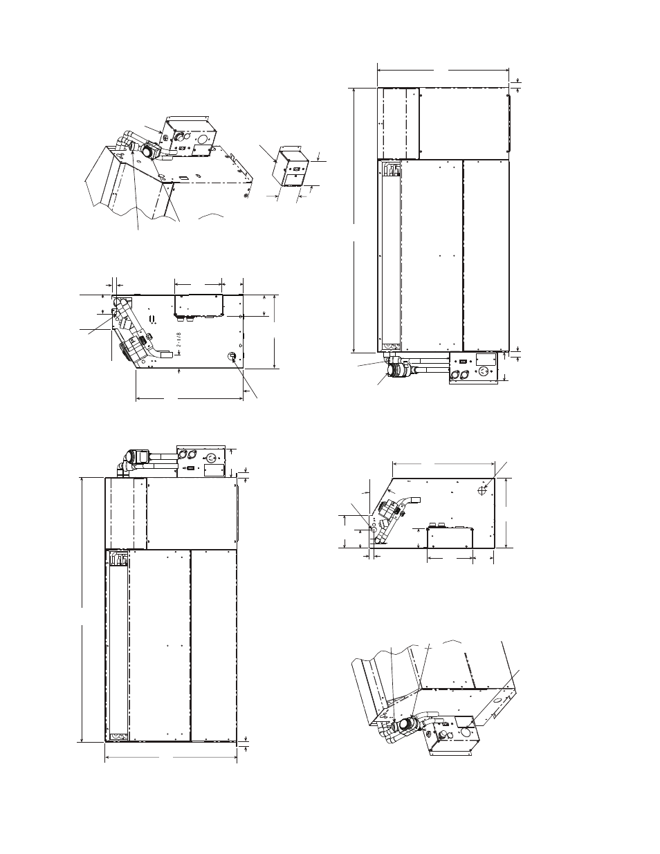
Fig.
1
3
— 50
PEC1
8 Ch
ass
is
Dimens
io
ns — Bot
tom Ret
urn
*If o
ptiona
l sub
base is selected, ad
d 125 mm to dimension
.
N
O
TES:
1.
Dimen
s
ions sho
w
n are in inch
es
. D
imens
ions in parentheses are in millimete
rs
.
2.
Optional autoflo
w v
a
lv
e
, motor
iz
e
d w
ater v
alv
e and disconn
ect b
o
x are sho
w
n.
Blower Deck
Blower Acce
ss
P
a
nel
Compre
ss
or
Acce
ss
P
a
nel
Control Box
46.98
(1
193)
4.49
(1
14)
0.75
(19)
0.75
(19)
*
20.50
(521)
Hard Wire
Power
S
upply
Blower Deck
Blower Acce
ss
P
a
nel
Compre
ss
or
Acce
ss
P
a
nel
Control Box
0.75
(19)
0.75
(19)
4.46
(1
13)
*
20.50
(521)
46.98
(1
193)
Conden
s
ate
5/
8
" ID V
(15.
8
mm)
inyl Ho
s
e
Optional
Motorized
W
ater V
alve
Optional
Autoflow
V
alve
Optional
Di
s
connect Box
(mo
u
nted to c
ab
inet
not ch
ass
is
)
Optional
Motorized
W
ater V
alve
Optional
Autoflow
Va
lv
e
7.5
(191)
0.87
(22)
1
1.54
(293)
3.43
(87)
*16.66
(423)
30˚
3.01
(76)
(136)
*
3.56
(90)
11
.5
4
(293)
*16.66
(423)
30˚
0.87
(22)
3.01
(76)
5.36
(136)
Conden
s
ate
5/
8
" ID Vinyl Ho
s
e
7.50
(191)
3.42
(87)
*
3.56
(90)
Optional
Motorized
W
ater V
alve
Optional
Autoflow
Valve
Optional Di
s
connect
Only Box
(All Config
u
ra
tion
s
)
Power
su
pply enter
s
Bottom of Box
4.46
(113)
4.56
(116)
Optional Fu
s
ed
Di
s
connect Box
(mo
u
nted to c
ab
inet
not ch
ass
is
)
Power
su
pply enter
s
Bottom of Box
Power
su
pply enter
s
Bottom of Box
Hard Wire
Power
S
upply
Ri
gh
t Hand
Con
fig
uratio
n
L
e
ft Hand
Con
fig
uratio
n
a50-834
9