Carrier 50PEC09-18 User Manual
Page 17
17
Step 2 — Check Unit —
Upon receipt of shipment at
the jobsite, carefully check the shipment against the bill of lad-
ing. Make sure all units have been received. Inspect the carton
or crating of each unit, and inspect each unit for damage. En-
sure the shipping company makes proper notation of any short-
ages or damage on all copies of the freight bill. Concealed
damage not discovered during unloading must be reported to
the shipping company within 15 days of receipt of shipment.
NOTE: It is the responsibility of the purchaser to file all neces-
sary claims with the shipping company.
STORAGE
Upon the arrival of equipment at the jobsite, immediately
store units in their shipping cartons in a clean, dry area. Store
units in an upright position at all times. Stack units a maxi-
mum of 3 units high. Use pallets to separate each layer of
units. DO NOT remove equipment from shipping cartons
until equipment is required for installation.
UNIT PROTECTION — Cover console units on the jobsite
with either shipping cartons, vinyl film, or an equivalent
protective covering. Cap the open ends of pipes stored on the
jobsite. In areas where painting, plastering, or the spraying of
fireproof material has not been completed, all due precautions
must be taken to avoid physical damage to the units and con-
tamination by foreign material. Physical damage and contami-
nation may prevent proper start-up and may result in costly
equipment clean-up.
Examine all pipes, fittings, and valves before installing any
of the system components. Remove any dirt found on these
components.
Step 3 — Mount Unit
1. Unpack the unit from the shipping carton. Remove the
front cabinet by lifting up and away from the backplate.
Protect the cabinet from damage during installation by re-
turning it to its original vinyl pack until required.
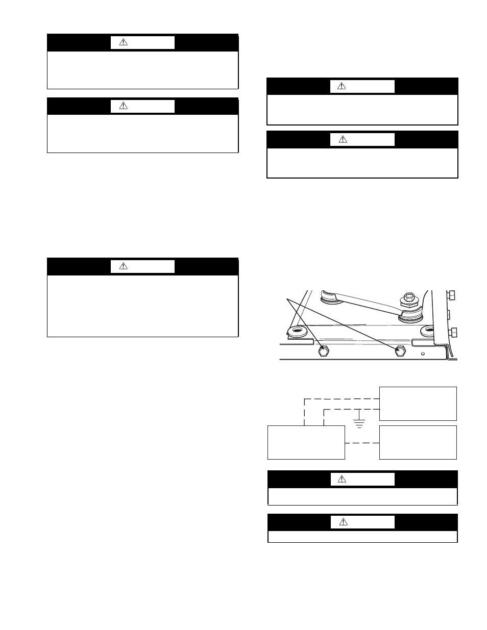
2. Remove compressor isolation plate shipping bolts (4), as
shown in Fig. 15.
3. Using a carpenter’s square and a level, ensure the unit
is level. Shim the unit if necessary to assure proper
installation.
Poor or inadequate installation may result in noisy
unit operation or unattractive appearance.
4. Select the proper fasteners to connect the backplate se-
curely to the wall.
5. Fasten the backplate onto the wall through the screw holes
located in the back flange. Secure the subbase in place.
Step 4 — Wire Electrical Connections
All field-installed wiring, including the electrical ground,
MUST comply with National Electrical Code (NEC, U.S.A.)
as well as all applicable local codes. In addition, all field wiring
must conform to the Class II temperature limitations described
in the NEC.
Consult the unit wiring diagram located on the inside of the
compressor access panel to ensure proper electrical hookup. The
installing (or electrical) contractor must make the field connec-
tions shown in Fig. 16 when using field-supplied disconnect.
Refer to unit wiring diagrams Fig. 17-24 for a schematic of
the field connections, which must be made by the installing (or
electrical) contractor. Operating voltage must be within voltage
range shown in Table 2.
CAUTION
All refrigerant discharged from this unit must be recovered
without exception. Technicians must follow industry
accepted guidelines and all local, regional, and national
statutes for the recovery and disposal of refrigerants.
CAUTION
When a compressor is removed from this unit, system
refrigerant circuit oil will remain in the compressor. To
avoid leakage of compressor oil, the refrigerant lines of the
compressor must be sealed after it is removed.
CAUTION
DO NOT store or install console units in corrosive environ-
ments or in locations subject to temperature or humidity
extremes (e.g., attics, garages, rooftops, etc.). Corrosive
conditions and high temperature or humidity can signifi-
cantly reduce performance, reliability, and service life.
Always move units in an upright position. Tilting units on
their sides may cause equipment damage.
WARNING
To avoid possible injury or death due to electrical shock,
open the power supply disconnect switch and secure it in
an open position during installation.
CAUTION
Use only copper conductors for field-installed electrical
wiring. Unit terminals are not designed to accept other
types of conductors.
SHIPPING
BOLTS
Fig. 15 — Remove 4 Shipping Bolts on
Compressor Isolator Plate
FIELD SUPPLIED
DISCONNECT SWITCH
ROOM THERMOSTAT
HEAT PUMP
A
B
A = Two power wires.
B = 1 heat/1 cool/manual or auto changeover remote 24-V thermostat.
NOTE: All customer-supplied wiring to be copper only and must conform to
national and local electrical codes. Wiring shown with dashed lines must be
field-supplied and field-installed. “B” wiring only required with systems using
remote-mounted thermostats.
Fig. 16 — Typical Field-Installed Wiring
WARNING
Disconnect electrical power source to prevent injury or death from elec-
trical shock.
CAUTION
Use copper conductors only to prevent equipment damage.