Carrier 50PEC09-18 User Manual
Page 16
16
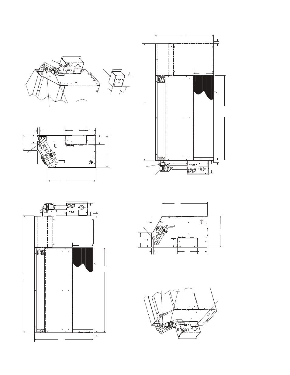
Fig.
1
4
— 50
PEC1
8
Ch
ass
is
Dimens
ions — Fr
ont
Re
tur
n
NO
TES:
1.
Dimension
s
sho
w
n a
re in inches
. Dimens
ions in pare
nthese
s
are in
millimeters
.
2.
Optional a
utoflo
w
v
alv
e
, moto
ri
z
ed w
ater v
alv
e and disconnect bo
x are
sho
w
n.
3.
Cha
s
sis can mount dire
ctly o
n floo
r.
Blower Deck
Compre
ss
or
Acce
ss
P
a
nel
Control Box
46.98
(1
193)
4.49
(1
14)
0.75
(19)
0.75
(19)
20.50
(521)
Hard Wire
Power
S
upply
Blower Deck
Filter
Compre
ss
or
Acce
ss
P
a
nel
Control Box
0.75
(19)
0.75
(19)
4.46
(1
13)
20.50
(521)
46.98
(1
193)
Optional
Motorized
W
ater V
alve
Optional
Autoflow
Va
lv
e
Optional
Di
s
connect Box
(mo
u
nted to c
ab
inet
not ch
ass
is
)
Optional
Motorized
W
ater V
alve
Optional
Autoflow
V
alve
7.5
(191)
0.87
(22)
1
1.54
(293)
3.43
(87)
16.66
(423)
30˚
3.01
(76)
3.56
(90)
11
.5
4
(293)
16.66
(423)
30˚
0.87
(22)
3.01
(76)
5.36
(136)
7.50
(191)
3.42
(87)
3.56
(90)
Optional
Motorized
W
ater V
alve
Optional
Autoflow
Valve
Optional Di
s
connect
Only Box
(All Config
u
ra
tion
s
)
Power
su
pply enter
s
Bottom of Box
4.46
(113)
4.56
(116)
Optional Fu
s
ed
Di
s
connect Box
(mo
u
nted to c
ab
inet
not ch
ass
is
)
Power
su
pply enter
s
Bottom of Box
Power
su
pply enter
s
Bottom of Box
Hard Wire
Power
S
upply
Blower
S
creen
Blower
S
creen
Filter
36.00
(914)
7.38
(187)
5.36
(187)
7.38
(187)
36.00
(914)
Ri
gh
t Hand
Con
fig
uratio
n
L
e
ft Hand
Con
fig
uratio
n
a50-8350