Carrier 50PEC09-18 User Manual
Page 26
26
OPTIONAL WALL-MOUNTED THERMOSTAT —
The 50PEC water source heat pump units are built with stan-
dard internal thermostats in either manual changeover (MCO)
or automatic changeover (ACO) configuration. Refer to
Fig. 17-20.
When desired, the unit can be furnished with a 24-v control
circuit which is field wired to a Carrier-supplied accessory re-
mote thermostat. Most heat pump thermostats can be used with
the controller. Use a thermostat with Y, G, O and W outputs.
Refer to unit wiring diagrams in Fig. 21 and 22 and Aqua-
zone™ Controls, Operation, and Troubleshooting Instructions
for additional information.
Vendor installation instructions and additional installation
information is shipped with each thermostat.
NOTE: Low-voltage wiring between the unit and the wall ther-
mostat must comply with all applicable electrical codes
(i.e., NEC and local codes), and be completed before the unit is
installed.
Table 3 lists recommended wire sizes and lengths to install
the thermostat. The total resistance of low-voltage wiring must
not exceed 1 ohm. Any resistance in excess of 1 ohm may
cause the control to malfunction because of high voltage drop.
Table 3 — Recommended Thermostat Wire Sizes
*Length = Physical distance from thermostat to unit.
OPTIONAL PREMIERLINK™ CONTROLLER — This
direct digital controller (DDC) allows the water source heat
pump to be incorporated into a Carrier Comfort Network
®
(CCN) system installation. PremierLink control is factory-
installed with the Complete C controller, or field-installed with
the Deluxe D control option. Refer to Fig. 23 and 24.
Step 6 — Install Supply and Return Piping
SUPPLY AND RETURN HOSES — Optional pressure-rated
hose assemblies are available for use with units. Use the fol-
lowing guidelines when installing supply and return hose
assemblies.
1. Install supply and return hoses fitted with swivel-joint
fittings at one end to prevent the hose from twisting.
2. Use male adapters to secure the hose assembly to the unit
and the riser.
3. Do not allow the hose to twist during installation. Twist-
ing may damage the hose wall or the rubber compound.
4. Use pipe joint compound sparingly on the fitting adapt-
ers’ male pipe threads.
5. Prevent sealant from reaching the joint’s flared surfaces.
6. Do not use pipe joint compound when Teflon* thread
tape is pre-applied to hose assemblies or when flared-end
connections are used.
7. Maximum torque that may be applied to brass fittings is
40 N
m. When a torque wrench is not used, tighten brass
fittings finger-tight plus one quarter turn.
8. Tighten steel fittings as necessary.
9. Use shut-off/balancing valves, flow indicators, and drain
tees in the supply runout and return at each floor to aid in
loop balancing and servicing.
SUPPLY AND RETURN PIPING — System piping MUST
comply with all applicable codes.
1. Install a drain valve at the base of each supply and return
riser to enable system flushing at start-up and during rou-
tine servicing.
2. Install shut-off/balancing valves and unions at each unit
to allow unit removal for servicing.
NOTE: If flex hoses are used, unions are not necessary.
3. Install strainers at the inlet of each system circulating
pump.
4. Before making the final water connections, flush the sys-
tem as described in the Pre-Start-Up section of this
manual. After flushing the system, connect piping and
hoses to the proper supply, return and condensate connec-
tions of the unit.
NOTE: When necessary, use adapters to connect hoses.
5. Install any other system components, as required, follow-
ing manufacturer’s instructions.
6. Reinstall the front cabinet by carefully lowering the front
cabinet over the chassis onto the backplate.
Step 7 — Install Condensate Piping —
Connect
the unit condensate drain to the building condensate drain with
a flexible, nonpressure-rated
5
/
8
-in. (16 mm) ID plastic hose.
Avoid kinks in this hose to ensure an unobstructed flow of con-
densate from the unit to the drain.
The horizontal run of the condensate hose is usually too
short to pose any drainage problems, however, the horizontal
run of condensate line should be pitched at least 10 mm for ev-
ery 1 m of run (in the direction of flow). Avoid low points and
unpitched piping since dirt collects in these areas and may
cause stoppage and overflow.
Field installation of a trap or vent is not required unless
specified by local codes. The 50PEC units are designed in a
blow-thru configuration. The condensate drain pan is located
on the outlet side of the blower so that the pressure in the drain
pan is higher than the atmospheric pressure.
WIRE SIZE
MAX WIRE LENGTH*
18-Gage
20 m
16-Gage
35 m
14-Gage
60 m
CAUTION
To ensure proper functioning of unit and system, be sure to
connect entering water to upper pipe on right-hand units.
On left-hand units, connect entering water to lower pipe.
Failure to do so could result in equipment damage.
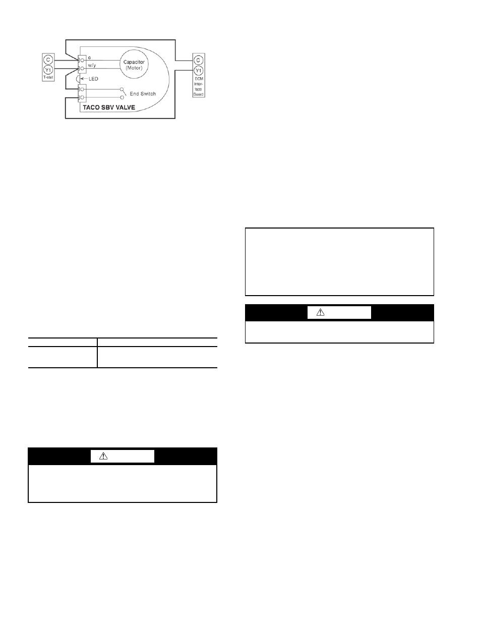
Fig. 28 — Taco SBV Valve Wiring
a50-8442
IMPORTANT: Since loop temperatures are normally
between 15.6 C and 32.2 C, pipe sweating and heat loss do
not occur at normal ambient temperature conditions. Insu-
lation must be installed on loop water piping on those sec-
tions that run through unheated areas or are located outside
the building. If loop temperatures are expected below the
ambient dew point, the optional internal insulation
(extended range) package must be ordered.
CAUTION
DO NOT bend or kink supply lines or hoses. Damage to
unit may result.
* Registered trademark of DuPont.