6 wire routing – SilentKnight 5129 Digital Alarm Communicator Transmitter User Manual
Page 13
Panel Description and Installation
150805
9
3.3.6
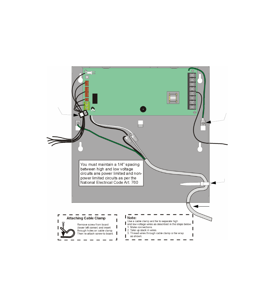
Wire Routing
High voltage and low voltage inputs must be separated by at least one-quarter inch and must be wired through
different knockout holes in the fire control cabinet to maintain the separation.
Figure 3-2 below shows an example of how to route the wire if you are using the model 5129. If you are using
the 5128, refer to the fire control panel installation manual for wire routing instructions.
Figure 3-2 Routing Wire for the 5129
Cable Clamp
From AC
Must be enclosed
in conduit.
See instructions
Below
To Telco
Lines
Cable Tie
Board Ground
This manual is related to the following products:
See also other documents in the category SilentKnight Safety:
- 5104 Digital Alarm Communicator Transmitter 6 Zone (48 pages)
- 5217 10-Zone Expander for 5208 (2 pages)
- 5220 Direct Connect Module (2 pages)
- 5235 Remote Annunciator for 5208 (2 pages)
- 5280 Status Display Module for 5208 (2 pages)
- 5495 6A Distributed Power Module (52 pages)
- 5496 6A Intelligent Remote Power Supply (38 pages)
- 5499 9A Distributed Power Module (56 pages)
- 5600 (114 pages)
- 5660 Silent Knight Software Suite (28 pages)
- 5670 IntelliKnight Facility Management Software (24 pages)
- 5700 (180 pages)
- 5808 (180 pages)
- 5815RMK Remote Mounting Kit (2 pages)
- 5815XL Signal Circuit Expander (2 pages)
- 5820XL-EVS (236 pages)
- 5824 Serial/Parallel Module (2 pages)
- 5860/5860R Remote Annunciator (2 pages)
- 5865-3/5865-4 Remote LED Annunciator (2 pages)
- 5880 LED Driver Module (2 pages)
- 5883 Relay Interface Board (4 pages)
- 5895XL 6A Intelligent Remote Power Supply (56 pages)
- B200S Intelligent Sounder Base with CO Support (4 pages)
- B200S-LF - Low Frequency Intelligent Sounder Base (4 pages)
- B200SR Sounder Base (4 pages)
- B200SR-LF Low Frequency Intelligent Sounder Base (4 pages)
- B210LP 6 Mounting Base (2 pages)
- B224BI 6 Mounting Base w/Built-in Isolator (2 pages)
- B224RB 6 Mounting Base w/Built-in Relay (4 pages)
- B501 4 Mounting Base (2 pages)
- Central Station Monitoring List (1 page)
- Document Revision History (4 pages)
- EVS (74 pages)
- EVS-CE4 (2 pages)
- EVS-RVM (2 pages)
- EVS-VCM (2 pages)
- FFT (1 page)
- FFT-24 (2 pages)
- FFT-24 Installation (1 page)
- FFT-FPJ (1 page)
- FFT-HSC (1 page)
- FFT-STSS and FFT-STSR (2 pages)
- HFS-D (4 pages)
- HFS-MM (1 page)