Warning – Reznor P6SP Unit Installation Manual User Manual
Page 8
8
1. Measure the line voltages
of your 3-phase power
supply where it enters the
building and at a location
that will only be dedicated
to the unit installation. (at
the units circuit protection
or disconnect).
Example
:
AB = 451V
BC = 460V
AC = 453V
In this example, the measured line voltages were
451, 460, and 453. The average would be 454 volts
(451 + 460 + 453 = 1,364 / 3 = 454).
Example:
From the values given in step 1, the BC voltage (460V)
is the greatest difference in value from the average:
460 - 454 = 6
454 - 451 = 3
454 - 453 = 1
Highest Value
max voltage deviation
from average voltage
= 100 x
average voltage
% Voltage Imbalance
6
454
100 x
= 1.32%
Example:
unit. Use proper code agency listed conduit and a conduit
connector for connecting the supply wires to the unit and
for obtaining proper grounding. Grounding may also be
accomplished by using the grounding lug provided in the
control box.
Low Voltage Connections - Thermostat
A two stage cooling 24 VAC thermostat is required for
these units. Several options are available for a room
thermostat depending on the accessories installed with
the unit. Select a thermostat which operates in conjunction
with the installed accessories. The thermostat should be
mounted about five feet above the floor on an inside wall.
The thermostat should be kept away from drafts, slamming
doors, lamps, direct sunlight and the supply air flow.
To install the thermostat:
1. Position the subbase on an inside wall and mark the
mounting holes and thermostat cable openings.
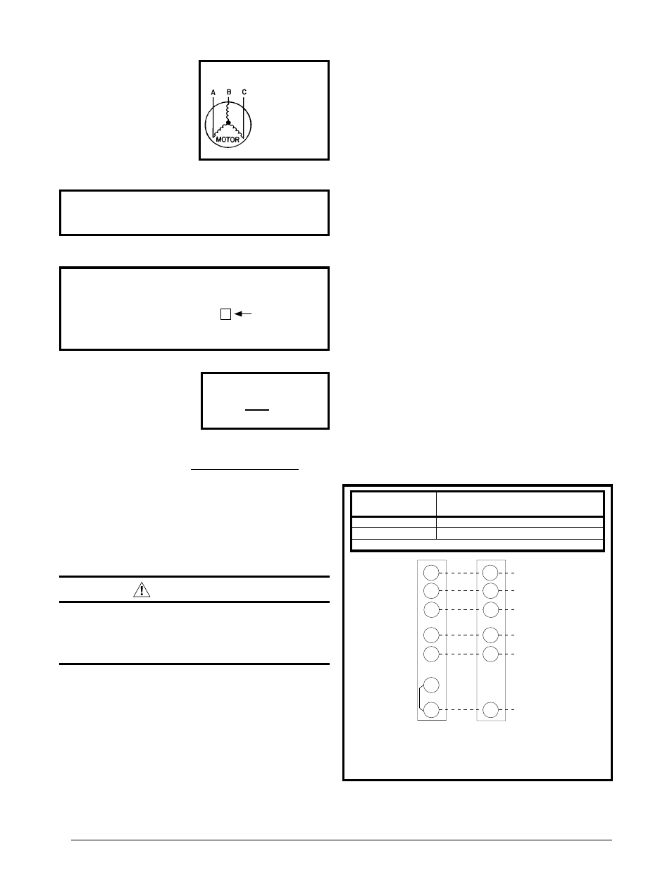
2. Cut out the cable opening and route the thermostat
cable from the unit’s low voltage compartment to the
thermostat location. The thermostat cable is supplied
by the installer. See Figure 8 for recommended wire
size.
3. Connect the cable leads to the subbase or thermostat
terminals and to the unit’s low voltage terminal block
as shown in Figure 8. System wiring diagrams are also
provided on the inside of the control access panel and
in Figures 13 - 16 (pages 21 - 22).
4. Secure the subbase or thermostat to the wall using
screws provided with the thermostat.
5. Install the correct thermostat housing to subbase.
6. Refer to thermostat instruction sheet for complete
detailed mounting and operating information.
3. Determine the maximum deviation: See example.
2. Determine the average voltage in the power supply.
Figure 8. typical connections -
2 stage cool / 1 stage Heat t-stat
Y1
Y2
W
1
/E
G
RH
RC
Y1
Y2
W
1
/E
G
R
Indoor Thermostat
Sub-Base
Unit Low Voltage
Terminal
24 V Hot
Blower
Emer. Heat
Stage 2
Heat/Cool
Stage 1
Heat/Cool
24 V Com
C
C
t-stat Wire
Gauge
recommended t-stat Wire
length - Ft. (unit to t-stat)
18 Ga.
0 - 60
16 Ga.
61 - 130
Field Supplied Wiring - - - - - Use Solid Class II Copper Wire
notE: If thermostat has one combined “O/B” Terminal and an
Economizer is installed, see Economizer Installation Instructions for
unit wiring change for proper operation.
4. Determine percent of
voltage imbalance by
using the results from
steps 2 & 3 in the following
equation.
The amount of phase imbalance (1.32%) is satisfactory
since the amount is lower than the maximum allowable
2%. Please contact your local electric utility company if
your voltage imbalance is more than 2%.
Grounding
WarnInG:
the unit cabinet must have an uninterrupted or
unbroken electrical ground to minimize personal
injury if an electrical fault should occur. Do not
use gas piping as an electrical ground
!
This unit must be electrically grounded in accordance
with local codes or, in the absence of local codes, with
the National Electrical Code (ANSI/NFPA 70) or the CSA
C22.1 Electrical Code. Use the grounding lug provided in
the element access compartment for grounding the unit.
Line Voltage Connections
Provide power supply for the unit in accordance with the
unit wiring diagram, and the unit rating plate. Connect
the line-voltage leads to the corresponding terminals on
the terminal block inside the control compartment. Use
only copper wire for the line voltage power supply to this