Blower performance tables, Table legend – Reznor P6SP Unit Installation Manual User Manual
Page 23
23
unit Model #
Motor
Hp
E.s.P. range
(in-Wg)
Blower rpm
range (DF)
Down-flow
Kit
Blower rpm
range (HF)
Horizontal
Kit
-072C
1.5 Hp
0.8 - 1.6
931 - 1189
920609
926 - 1159
920609
-072D
920560
920560
-090(C/D)a
2 Hp
0.1 - 1.7
884 - 1216
921481
874 - 1209
921481
-120(C/D)a
2 Hp
0.1 - 1.4
650 - 911
921645
659 - 919
921645
notE: Refer to the P6SP TSL or Accessory Kit Installation Instructions for actual blower charts
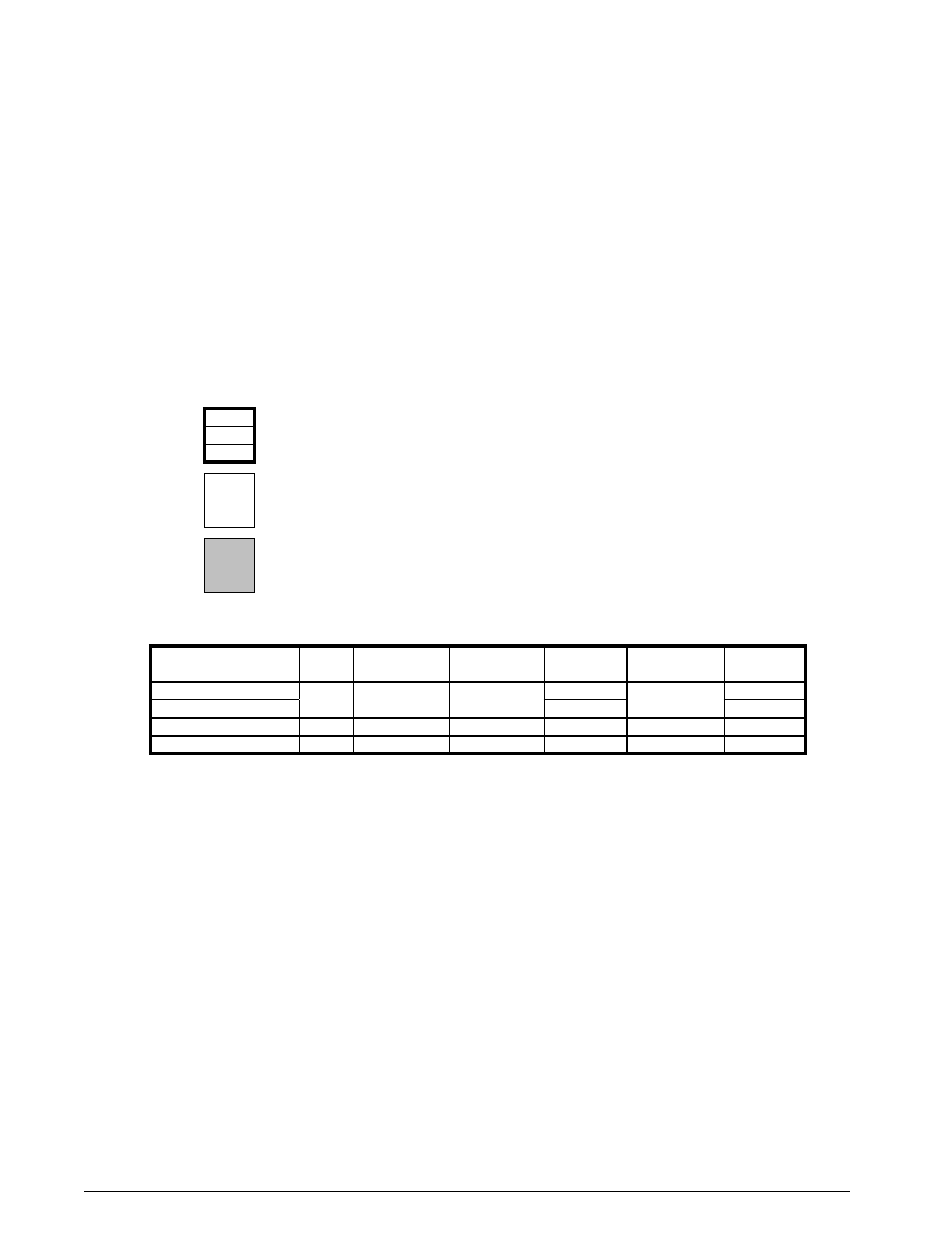
table 4. P6sP series alternate accessory Blower Drives
Blower Performance tables
This equipment is outfitted with a belt driven blower assembly in order to accommodate a large variety of duct
configurations and airflow selections. The blower has been factory inspected for proper alignment, operation and
rotational direction prior to the drive motor being situated in the shipping position. The blower drive belt is located
with these instructions and must be installed by the service technician. For a more detailed explanation of belt driven
blower drives and the operation of their components please refer to any of the installation instructions listed below
for the high static drive kits.
The factory standard drive installed in these units has been set to deliver 400 Cfm/ton at an External Static Pressure
(ESP) of 0.25-0.30 in-Wg. Tables 5-10 show the full blower curves of these drive configurations and can be utilized
to easily set the adjustable motor sheave for alternate configurations. Refer to the Legend below for a description
of the table information. Once a sheave setting has been made, always inspect the blower amp draw to ensure that
it is less then the service factor amps listed on the motor. For systems that include a large number of accessories
or have very restrictive duct systems, alternate drive kits are available – refer to table 4 below for the applicable
kits. The full blower curves for the HSD kits can be found in the applicable kit installation instructions or in the unit
technical service literature.
3862
1159
Indicates a recommended unit operational point
3.03
3493
Indicates an allowable setting that is not recommended for unit operation
†
† These operational points should be carefully examined by the installer for proper unit setup and heater operation if used.
1017
2.07
Indicates a setting that is not permitted for unit operation
table
legend