Wiring dia gram, Three phase 60 hz, P6sp series 6-10t – Reznor P6SP Unit Installation Manual User Manual
Page 22
22
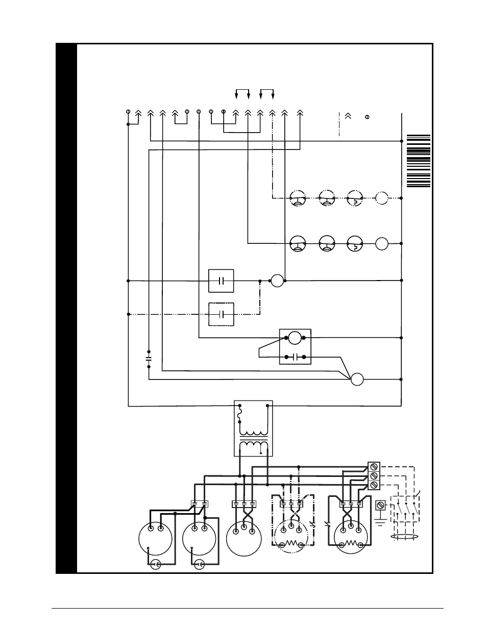
Figure 14. ladder Diagram for P6sP-072/090/120 (c/D) series
Three Phase 60 Hz.
4.
For suppl
y wire ampacities and o
ver
current pr
otection,
see unit
rating label
.
5.
On
“C”
Series Models on
ly
. For 208V operation remo
ve wire fr
om
230V tap and place on 208V tap.
1.
Couper le courant
av
ant de faire letretien.
2.
Empl
oy
ez uniquement des conducteu
rs
en cuivre
.
WIRING DIA
GRAM
P6SP Series 6-10T
NO
TES:
1.
Disconnect all po
wer bef
ore servicing.
2.
For suppl
y connections use copper conductor
s onl
y.
3.
If an
y of the original wire as supplied with the furnace
mu
st be replaced
,
it m
ust be replaced with wiring material ha
ving a temperature rating of
at least 105C.
CCH - Crankcase Heater
s,
Stage 1&2 Compressor
CC1&2 - Contacto
r, Stage 1&2 Compressor
IBC - Contactor
, Indoor Bl
ow
er Motor
OFC - Contactor
, Outdoor
Fa
n
R
C
T2
T3
T1
IBC
L1
L2
L3
GND
24V
Common
24V
Hot
Compressor 1
T2
T3
T1
CC2
Compressor 2
T2
T1
T3
CC1
Au
x.
Switch
(N.C
.)
CC2
Au
x.
Switch (N.C
.)
CC1
CCH1
CCH2
IBC
OFC
Y1
Factor
y
Jumper
CC2
CC1
LV
T-C (24V COM.)
Au
x.
Switch
(N.O
.)
IBC
Field Supplied Disconnect
(3Phase
Po
wer Only
)
F
or supply connections use
copper conductors only
.
Unit
Te
rminal
Bloc
k
Tr
ansf
or
mer
24V Sec.
Prima
ry
Outdoor F
an Motor
Outdoor F
an Motor
Indoor
Fa
n Motor
LVT - Lo
w
V
oltage
Te
rminal
HK - Heater Kit
E - Economiz
er
4 Amp
Circuit
Break
er
See Note
5
OFC
LV
T-
R
High
Pressure
Switchs
Ev
ap
.
Freez
estats
Lo
w
Pressure
Switchs
HK-4
Blo
we
r
Rela
y
CC
1
A
ux.
Switch
(N.O
.)
CC
2
A
ux.
Switch
(N.O
.)
2
1
3
4
LV
T-
Y1(Stage 1 Cool
)
HK-1
HK-2
HK-3
LV
T-
Y2(Stage 2 Cool
)
LV
T-
G
LV
T-
W1(Heat)
E-1
E-
9
E-
8
E-
2
E-
4
E-
5
Y2
Factor
y
Jumper
208-230/460
Volt
S
R
C
S
7111520
01/11
(Replaces 710747A,7107540
)
See Alter
nate OD
fa
n
wir
ing Diagram
B
- Indicates plug connection.
Letter Indicates which plug.
Number indicates pin location.
2 Stage Equipment Onl
y
- Indicates scre
w connection.