Neuspeed 49.10.95 User Manual
Page 4
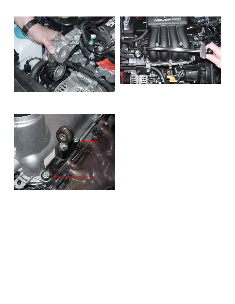
10. BELT TENSIONER REMOVAL: Using a 15mm open-end
wrench, rotate tensioner to release tension on belt and remove the
ribbed V-belt. Remove the three 13mm tensioner mounting bolts
and remove tensioner assembly.
12. SUPERCHARGER INSTALLATION: First assemble the
supplied new stainless steel/neoprene backed washers on the
supplied new (3) M6X25mm and (2)M6X95mm intake manifold
bolts. Ensure that the steel side of the washers are in contact with
the heads of the bolts, and apply a small amount of NEUSPEED
special grease to the neoprene side. With the Supercharger on the
bench, and the mounting flange vertical, position the intake
manifold gasket on the inlet runner flange and align ports. Be
very careful here because the gasket only fits one-way – double
check alignment of ports and bolt mounting holes! Insert bolts
into proper holes to hold gasket in place. Remove tape covering
lower intake ports, and lower Supercharger onto lower intake
runners. Carefully support backside of Supercharger until
you have run mounting bolts down and torqued to 44inch lbs.
(3.6 ft. lbs.). Now you must check to see if the Driver Side Rear
Support Bracket is in alignment with threaded hole on
Supercharger. Bolt MUST align perfectly with hole. If not,
determine amount of adjustment (up-or-down) to properly
position rod end. You will need to remove Supercharger, make
adjustment, re-torque bolts and try again. NOTE: Supercharger
MUST be torqued to proper setting BEFORE
checking/installing bolt! When you have a perfect fit, apply
Loctite and torque Supercharger Rear Support bolt M8X35mm to
15ft. lbs, and tighten jam nut on rod end if you made an
adjustment. NOTE: This step is very important – you MUST
take time to do it right!
11. DRIVER SIDE REAR SUPERCHARGER SUPPORT
BRACE INSTALLATION: We have assembled (mounting
bracket, insulated rod end, jam nut) to its approximate length.
Remove the two rear driver side valve cover nuts (10mm hex)
from area shown. Install bracket on valve cover studs with rod
end leaning forward. Install nuts. Torque to 7ft. lbs.
NOTE: The by-pass valve has been pre-installed and adjusted –
DO NOT change adjustment!
Page 4